Self-optimizing adaptive antenna

a technology of adaptive antenna and self-optimization, which is applied in the direction of thermoelectric devices, instruments, substation equipment, etc., can solve the problem of time-consuming process and achieve the effect of efficient optimization of positioning of receiving elements

Inactive Publication Date: 2010-05-18
USA AS REPRESENTED BY THE SEC OF THE NAVY THE
View PDF9 Cites 7 Cited by
  • Summary
  • Abstract
  • Description
  • Claims
  • Application Information

AI Technical Summary

Benefits of technology

[0007]It is an object of the present invention to provide a system and method for efficiently optimizing positioning of receiving elements of a variable antenna. More specifically, it is object of the present invention to provide an autonomous antenna system, which has the capability to self-optimize the reception of antenna signals. The system is able to optimize antenna element position, signal phase and signal strength from various antenna elements through the analysis of quality and strength of antenna signals by an artificial intelligence technique.

Problems solved by technology

Other methods may rate only a random sample of the population, as this process may be very time-consuming.

Method used


Image

  • Self-optimizing adaptive antenna
  • Self-optimizing adaptive antenna
  • Self-optimizing adaptive antenna

Examples


Embodiment Construction

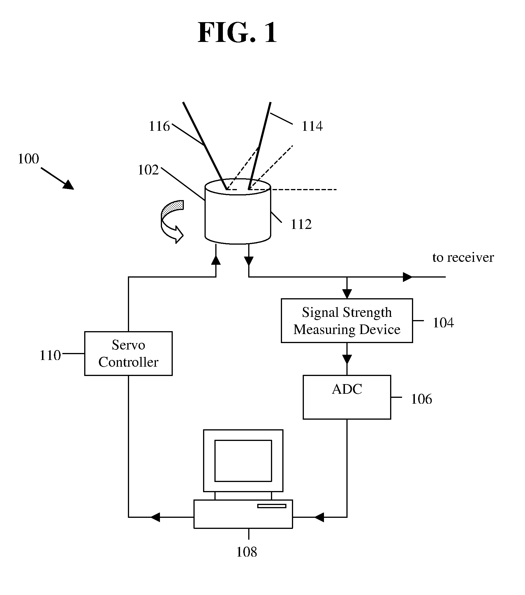
[0025]FIG. 1 illustrates an exemplary antenna system in accordance with the present invention. In the figure, antenna system 100 includes antenna 102, signal strength measuring device 104, analog to digital converter (ADC) 106, processing system 108, and servo controller 110.

[0026]Antenna 102 includes base 112, first receiving element 114 and second receiving element 116. Base 112 is rotatable through angle w and thus has a single degree of freedom. First receiving element 114 has a first end that is moveably connected to base 112 and a second end. Specifically, first receiving element 114 is rotatable about its first end through an angle φ1 in a plane parallel to the top of base 112 and through an angle θ1 in a plane perpendicular to the top of base 112. As such, first receiving element 114 has two degrees of freedom. Second receiving element 116 has a first end that is moveably connected to base 112 and a second end. Specifically, second receiving element 116 is rotatable about it...


PUM


Abstract

The present invention determines optimal positions of a variable antenna using an artificial intelligence-based genetic algorithm (GA). The GA acquires a fitness value for an individual of a genetic algorithm population by updating positions of the antenna. The population improves through an evolutionary computational process using a fitness measure based on the signal strength. At the end of the process, the system positions the antenna to the best position found by the GA. Therefore, the final position gives exceptionally clear reception for a chosen received frequency.

Description

CROSS-REFERENCE TO RELATED APPLICATIONS[0001]This application claims the benefit of priority under 35 U.S.C. §119(e) to provisional patent application Ser. No. 60 / 869,798, filed Dec. 13, 2006, the entire disclosure of which is incorporated herein.BACKGROUND OF THE INVENTION[0002]When communicating between electronic devices without wires, antennas are used to transmit information between the electronic devices. On the both ends, the antennas are designed to improve the signal strength. Optimizing antenna element properties such as signal phase, signal amplification, and element position minimize the loss of energy when transmitting and thus reduces the amount of power required to transmit the signal and improves the quality of the signal sent. Optimizing such properties for a receiving antenna yields similar results.[0003]Most antennas are designed in ideal laboratory conditions before they are connected to real devices. However, real operating conditions can deviate far from ideal ...

Claims


Application Information

Patent Timeline
Patent Type & Authority Patents(United States)
IPC IPC(8): H04M1/00H01Q11/12H04B7/14H04B1/04G01S5/02H01Q13/00H01Q3/00H01Q1/32
CPCG01S7/02H01Q3/2605H01Q3/04
Inventor HANLEY, BRIANOH, CHOONG K
Owner USA AS REPRESENTED BY THE SEC OF THE NAVY THE
Why Eureka
Try Eureka