Chain link for a circulating transport of a machine tool, and double end tenoner with guide chain formed from said chain links

a technology of chain link and machine tool, which is applied in the direction of transportation and packaging, conveyor parts, rollers, etc., can solve the problems of increased frictional corrosion, vibration or oscillations that are perceived detrimentally, and inadequate magnetic force direction in respect of vibration damping, so as to reduce the circulating workpiece support, and reduce the possibility of fretting corrosion

Active Publication Date: 2010-05-25
HOMAG HOLZBEARBEITUNGSSYST
View PDF55 Cites 4 Cited by
  • Summary
  • Abstract
  • Description
  • Claims
  • Application Information

AI Technical Summary

Benefits of technology

[0008]A workpiece support is provided over the rollers. At least one further roller is located at a distance in the direction of circulation of the chain link, i.e. from the front to the rear, from the pair of rollers. In this way, the rollers ensure stability against tipping around the transverse axis. The, at least one, further roller and the roller pair when rolling together draw a plane that acts as a reference plane for the disposal of one or a plurality of surfaces to create an improved air gap. A guide, guiding the chain link transversely to its direction of circulation, is also provided. It may have a transverse guide roll or be roller-free transverse to the direction of circulation of the chain link between the pair of rollers.
[0010]Alternatively, if a transverse roller is used, a ferromagnetic material is provided between the pairs of rollers observed in the direction of circulation, forming at least one surface at a distance from the end face of the axle pin for the transverse guide roller substantially parallel to the plane formed by the rollers and disposed at a distance from this plane in such a way that a two-dimensional air gap is formed there when the transport chain is in operation. This surface or these surfaces can be at a distance from the axle pin in the direction of circulation, but they can also surround it radially, but at a distance from it so that a two-dimensional parallel air gap is also formed at the end face of the axle pin. However, the air gap is spatially separated from the points where the chain links revolve, which reduces the possibility of fretting corrosion. According to the invention, the chain links in the present invention are used in continuous-throughfeed machines because of the predominantly series production involved, the high feed velocity of the workpieces through the machine and the influence of the lower circulating workpiece support on the quality of processing previously considered significant. The circulating transport chain which acts as a workpiece support here also circulates in a plane that is perpendicular to the transport chain of the workpiece. The previous requirement of synchronous running of the support or the right-hand and left-hand supports can be reduced with the help of the invention. With the improved vibration behavior, there is also less significance in the synchronization of the left-hand and right-hand support, as long as the parallelism of the workpiece transport is ensured. This is a noticeable advantage in the processing of workpieces with inkjet printers, for example, such that if the chain links according to the invention are used for the transport of the workpiece in inkjet or other print stations, the matrix spacing of the print is effectively ensured.

Problems solved by technology

In this prior art the problem was identified that, because of the spring preload on the previously known chains, vibrations or oscillations occur which are perceived detrimentally because of the generation of impact, noise and wear on the chains and their return devices.
The result is a magnetic force direction which is inadequate in respect of its damping of vibrations.
Furthermore, it has become clear that the provision of magnets in the area of the slot between the guide wheels and the track leads to increased frictional corrosion in long term operation (also known as fretting corrosion), which makes more frequent replacement of the components concerned necessary.
This is unsatisfactory in remedying the disadvantage of wear and the accompanying replacement of the worn components originally addressed.

Method used


Image

  • Chain link for a circulating transport of a machine tool, and double end tenoner with guide chain formed from said chain links
  • Chain link for a circulating transport of a machine tool, and double end tenoner with guide chain formed from said chain links
  • Chain link for a circulating transport of a machine tool, and double end tenoner with guide chain formed from said chain links

Examples


first embodiment

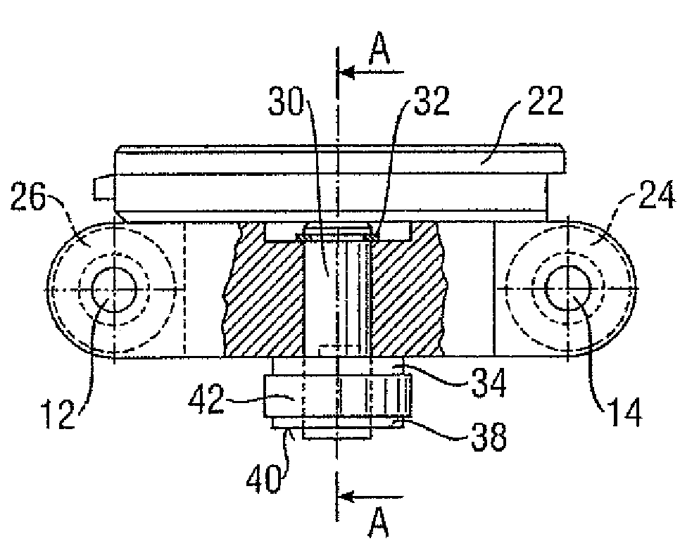
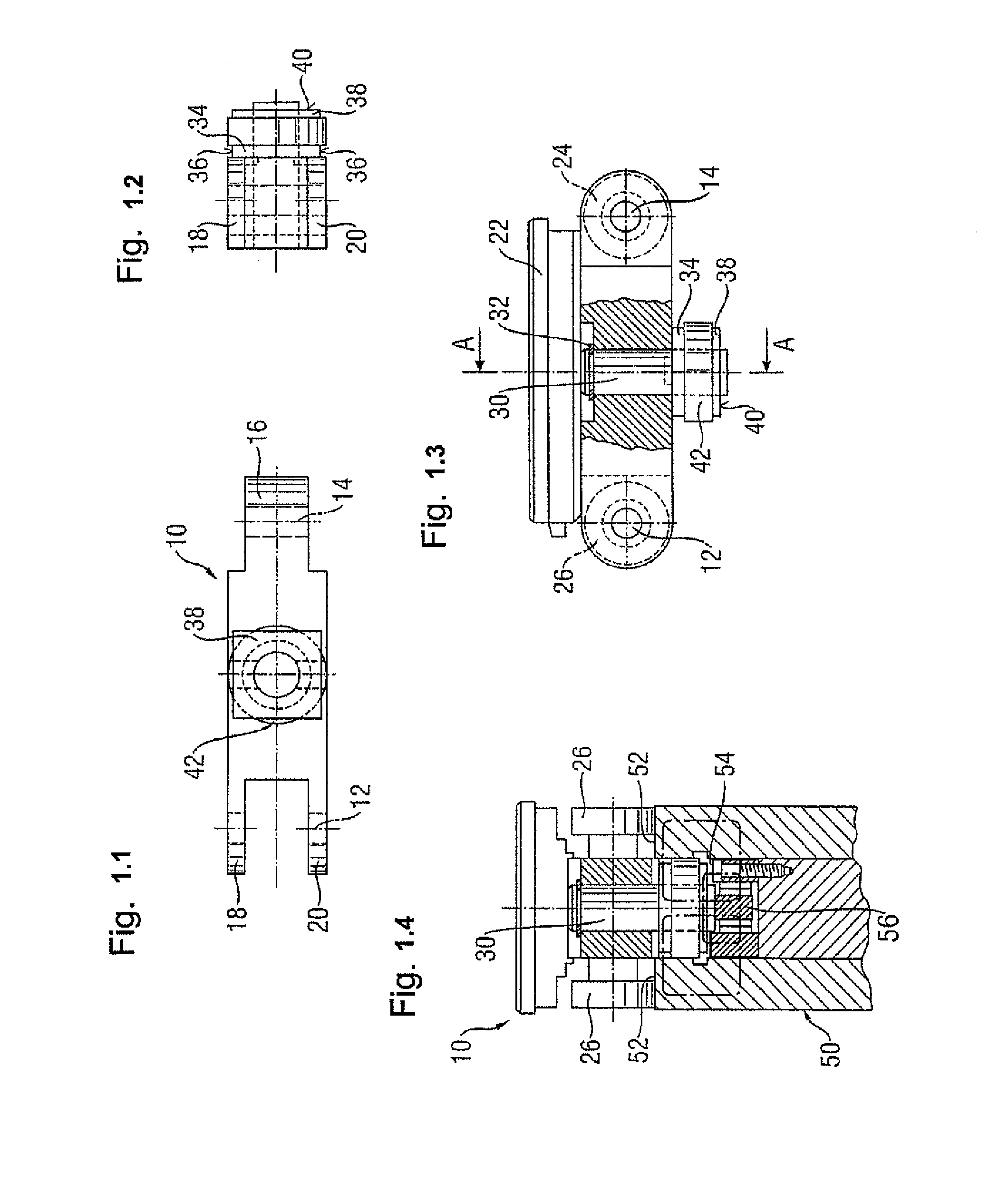
[0046]FIG. 1 shows the FIG. 1.1 shows a bottom view, in which the chain link can be seen in general at 10. Roller axes 12 and 14 extend transverse to the longitudinal extent of chain link 10 and are only shown schematically here. In order to provide a connection to the neighboring chain links and thus to form a chain, chain link 10 has in the generally known manner at one end a bearing bush 16 and at the other end, two axle journals 18, 20. The axle journals 18, 20 grip around the bearing bush 16 of an adjacent chain link, and so the adjacent chain links are fastened together by way of an axle or shaft for the rollers 24, 26 (FIG. 1.3).

[0047]FIG. 1.2 shows a front view of chain link 10, in which it is also possible to identify axle journals 18, 20. The rollers 24, 26 and the workpiece support 22 are clear from FIG. 1.3 which shows a side view of the chain link illustrated in FIG. 1.1. The workpiece support 22 lies above the roller axes 12, 14, here in accordance with the preferred ...

second embodiment

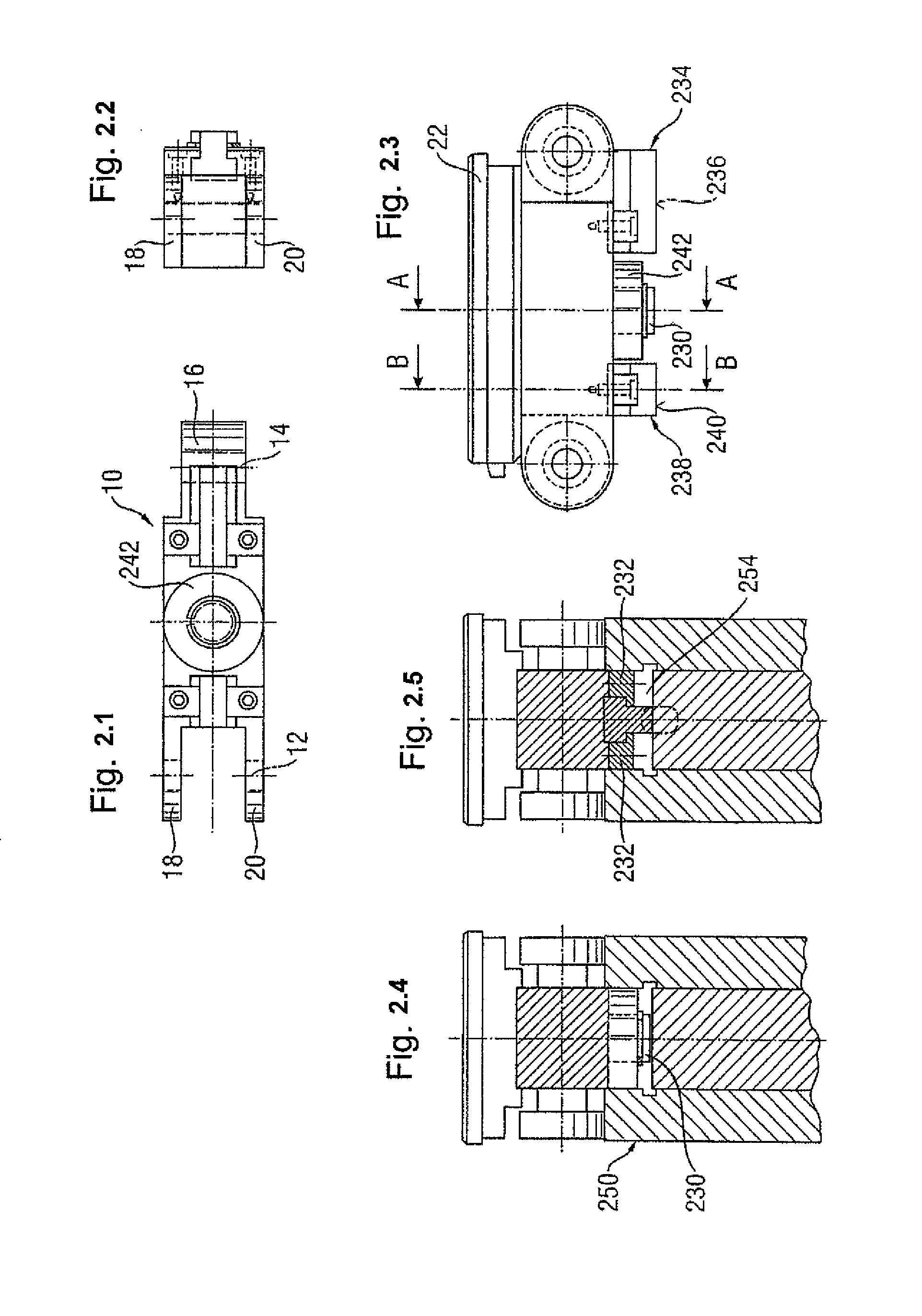
[0057]FIG. 2 shows a second embodiment, in which the views of FIGS. 2.1, 2.2, 2.3 correspond to those of FIGS. 1.1, 1.2 and 1.3. FIG. 2.4 shows a section line running through the centre axis of the axle pin 230 for the transverse guide roller 242, along the course of the section line A-A from FIG. 2.3. FIG. 2.5 shows an additional cross-section, corresponding to the course of the section line B-B in FIG. 2.3.

[0058]FIG. 2 shows that lands 234, 238 are provided at a distance in front of and behind the transverse guide roller 242 in the direction of the circulation of the chain link. In the embodiment according to FIG. 2, the lands are formed from angle iron pieces 232 and permanent magnets. The permanent magnets also have a surface on which in conjunction with the chain guide 250, specifically with the bed of the guide groove 254, an air gap is formed. The air gap faces of the lands are identified as 236 and 240 accordingly. In the embodiment according to FIG. 2, because the permanent...

third embodiment

[0059]Similar lands are implemented in the third embodiment in accordance with FIG. 3, with the views as FIGS. 3.1, 3.2 and 3.3 corresponding to the numbered views in FIGS. 1 and 2. FIG. 3.4 shows a cross-section through the centre axis of the axle pin stub 330 for a transverse guide roller in accordance with the course of the section line A-A as shown in FIG. 3.3. FIGS. 3.5 and 3.6 show a comparison of the cross-section along the section line B-B from cut-outs 3.3 once with and once without the lands 334 and 338.

[0060]From the comparison of FIGS. 3.4, 3.5 and 3.6 described below, it is clear how the provision of the lands 234, 238 positively influence the formation of the magnetic circuit. The comparison is made on the basis of the embodiment in accordance with FIG. 3, but is also correct for the other embodiments.

[0061]As FIG. 3.4 shows, without the lands 234, 238 it is impossible to clearly forecast whether the magnetic circuit will close itself through the linear contact between...


PUM


Abstract

The present invention discloses chain links for the circulating transport chain of a machine tool, which comprise: a pair of rollers which determine the direction of circulation of the chain link by way of the direction in which they roll, over the rollers which is or are placed at a distance from the pair of rollers in the direction of circulation of the chain link and draw a plane as they roll against the roller pair; and a transverse guide, guiding the chain link transverse to its direction of circulation and is either free from rollers transverse to the direction of circulation of the chain link between the pair of rollers or has a transverse guide roller.

Description

CROSS-REFERENCE TO RELATED APPLICATIONS[0001]This application claims priority to European patent application no. 06014463, filed Jul. 12, 2006, the disclosure of which is incorporated herein by reference in its entirety.TECHNICAL FIELD[0002]The present invention relates to a chain link for an endlessly circulating workpiece transport chain and to a continuous process machine used in the machining by chip removal of flat workpieces of wood, plastic or comparable materials, for instance a double end tenoner with one or two guide chains made from said chain links as a circulating workpiece support.PRIOR ART[0003]EP 1 479 944 A2 (Siemens Aktiengesellschaft) discloses a guide for a circulating transport chain built up of individual chain links. In this prior art the problem was identified that, because of the spring preload on the previously known chains, vibrations or oscillations occur which are perceived detrimentally because of the generation of impact, noise and wear on the chains a...

Claims


Application Information

Patent Timeline
Patent Type & Authority Patents(United States)
IPC IPC(8): B65G21/20
CPCB65G21/2009B65G17/38
Inventor GAUSS, ACHIMRATHGEBER, PETER
Owner HOMAG HOLZBEARBEITUNGSSYST
Why Eureka
Try Eureka