Rib support for wing panels

a technology for ribs and wing panels, applied in the direction of fuselages, fuselage bulkheads, transportation and packaging, etc., can solve the problems of a large crushing load on the ribs supporting the wing panels, a large buckling of the upper wing, and a source of costly rework

Active Publication Date: 2010-05-25
THE BOEING CO
View PDF13 Cites 26 Cited by
  • Summary
  • Abstract
  • Description
  • Claims
  • Application Information

AI Technical Summary

Benefits of technology

[0008]The present invention provides an innovative structure for the ribs to support the panels without an attachment between the rib and the stringer free flange or the web. The support is provided by rib shear ties installed directly to the stringer skin flange. The rib incorporates a cut away to allow the stringer to pass through the rib. The composite stringer is an ‘I’ section and is designed to be stable under compression, not requiring mechanical methods to prevent rolling over.
[0009]This design provides further benefit in that all drilling can be done from outside the wing box facilitating automation, allowing fabrication which is much easier, less costly, and less prone to rework.

Problems solved by technology

These loads and the resulting deflections produce upper wing compression buckling and a crushing load on ribs supporting the wing panels.
These designs are undesirable because they require installation while the wing box is being built.
Drilling holes inside an enclosed wing box presents many challenges and provides a source for costly rework.
Further, if this rib bolt design is applied to a composite wing structure, it creates interlaminar tension problems in the stringer radius.
This is a poor load path for the composite structure which may require reinforcement methods for the stringer radius adding more cost.

Method used


Image

  • Rib support for wing panels
  • Rib support for wing panels
  • Rib support for wing panels

Examples


Embodiment Construction

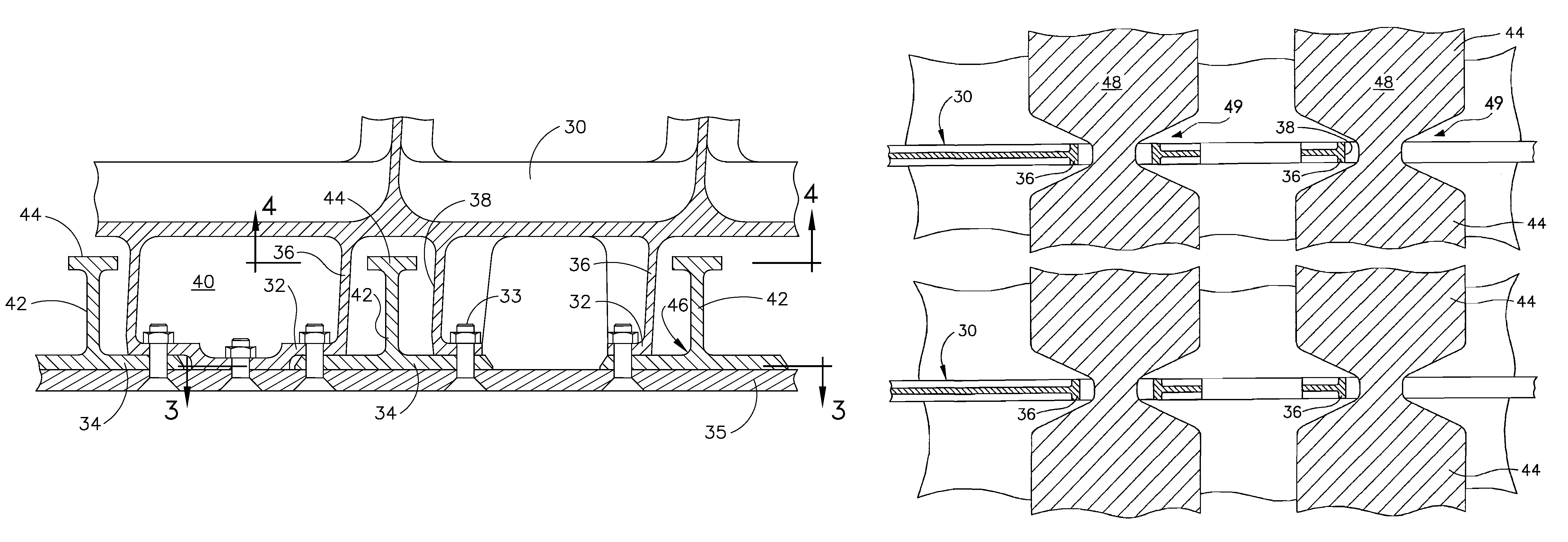
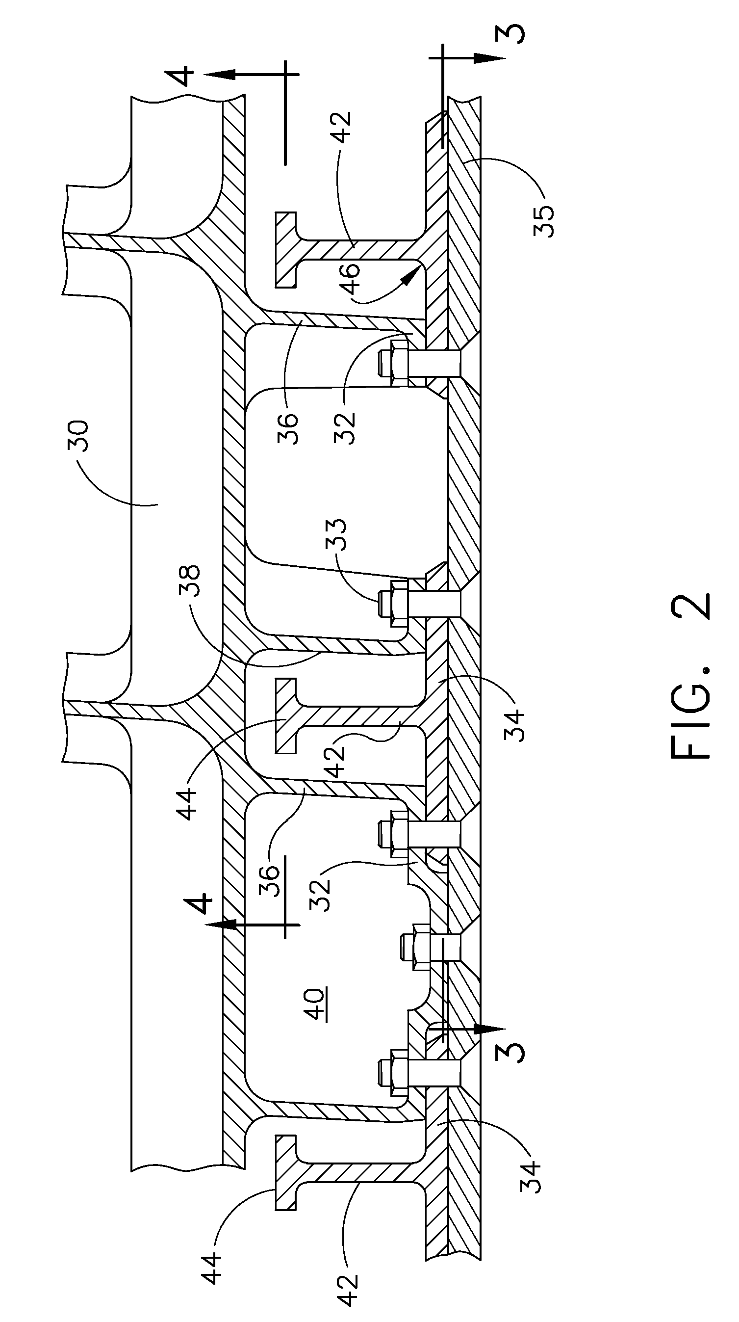
[0016]As shown in FIG. 2 the present invention provides a wing structure having ribs 30 which are fully shear tied. In the wing skin panels, stringer skin flanges 34 attach to shear ties 32 at an airfoil surface profile created by the rib using bolts or other combination tension / compression load path and disbond arrestment fasteners 33 which also attach the skin 35 for the embodiment shown.

[0017]The ribs are stiffened from the lower wing surface to the upper wing surface. To react to tension load pull off created by the stringer attachment to the shear ties at the ribs, the ribs have gussets 36 surrounding stringer cut aways 38 to help transfer skin panel attachment loads into the web 40 of the ribs while providing pass through of the stringers 42. These gussets act in concert with the rib stiffening for structural integrity of the ribs in conjunction with reacting to the pull off loads. For the embodiment shown in the drawings, the ribs are machined to provide the gussets and cutou...


PUM


Abstract

An innovative wing structure provides fibs to support skin panels without an attachment between the rib and the stringer free flange or the web. The support is provided by rib shear ties installed directly to the stringer skin flange. The rib incorporates a cut away to allow the stringer to pass through the rib. The composite stringer is an ‘I’ section and is stable under compression, not requiring mechanical methods to prevent rolling over.

Description

BACKGROUND OF THE INVENTION[0001]1. Field of the Invention[0002]This invention relates generally to the field of aircraft structural systems and more particularly to a rib structure and attachment system for composite wing panels.[0003]2. Description of the Related Art[0004]In aircraft structures, wing panels, which consist of skins and stringers, react wing bending loads. These loads and the resulting deflections produce upper wing compression buckling and a crushing load on ribs supporting the wing panels. The compression buckling capability for the panel is driven by geometry, rib spacing and stringer spacing. The boundary conditions for the panel are determined by the method of support the rib gives the skin / stringer.[0005]Traditional aluminum panel design as shown in FIG. 1 provided panel support by attaching the rib 10 to the stringer 12 by means of a series of rib bolts 14 between the free flange 16 of the stringers and the associated rib chord flange 18. Skins 20 are attache...

Claims


Application Information

Patent Timeline
Patent Type & Authority Patents(United States)
IPC IPC(8): B64C1/12
CPCB64C3/182B64C3/26B64C3/187
Inventor TANNER, RICHARD B.BURFORD, IAN C.GENDZWILL, THOMAS V.DOTY, GREGORY B.HUCK, JAMES R.WILSON, DEAN E.KORENAGA, BRIAN H.
Owner THE BOEING CO
Why Eureka
Try Eureka