Method and apparatus for Josephson distributed output amplifier

a distributed output amplifier and amplifier technology, applied in the field of wideband distributed amplifiers, can solve the problems of poor efficiency, low signal level, and high data ra

Active Publication Date: 2010-05-25
NORTHROP GRUMMAN SYST CORP
View PDF40 Cites 81 Cited by
  • Summary
  • Abstract
  • Description
  • Claims
  • Application Information

AI Technical Summary

Problems solved by technology

A major drawback of the conventional distributed amplifier is poor efficiency because power matching and phasing cannot be achieved at the same time.
However, because signal levels are so low and data rates are so high, establishing data links to conventional electronics, at low bit error rate, has been proved difficult.

Method used


Image

  • Method and apparatus for Josephson distributed output amplifier
  • Method and apparatus for Josephson distributed output amplifier
  • Method and apparatus for Josephson distributed output amplifier

Examples


Embodiment Construction

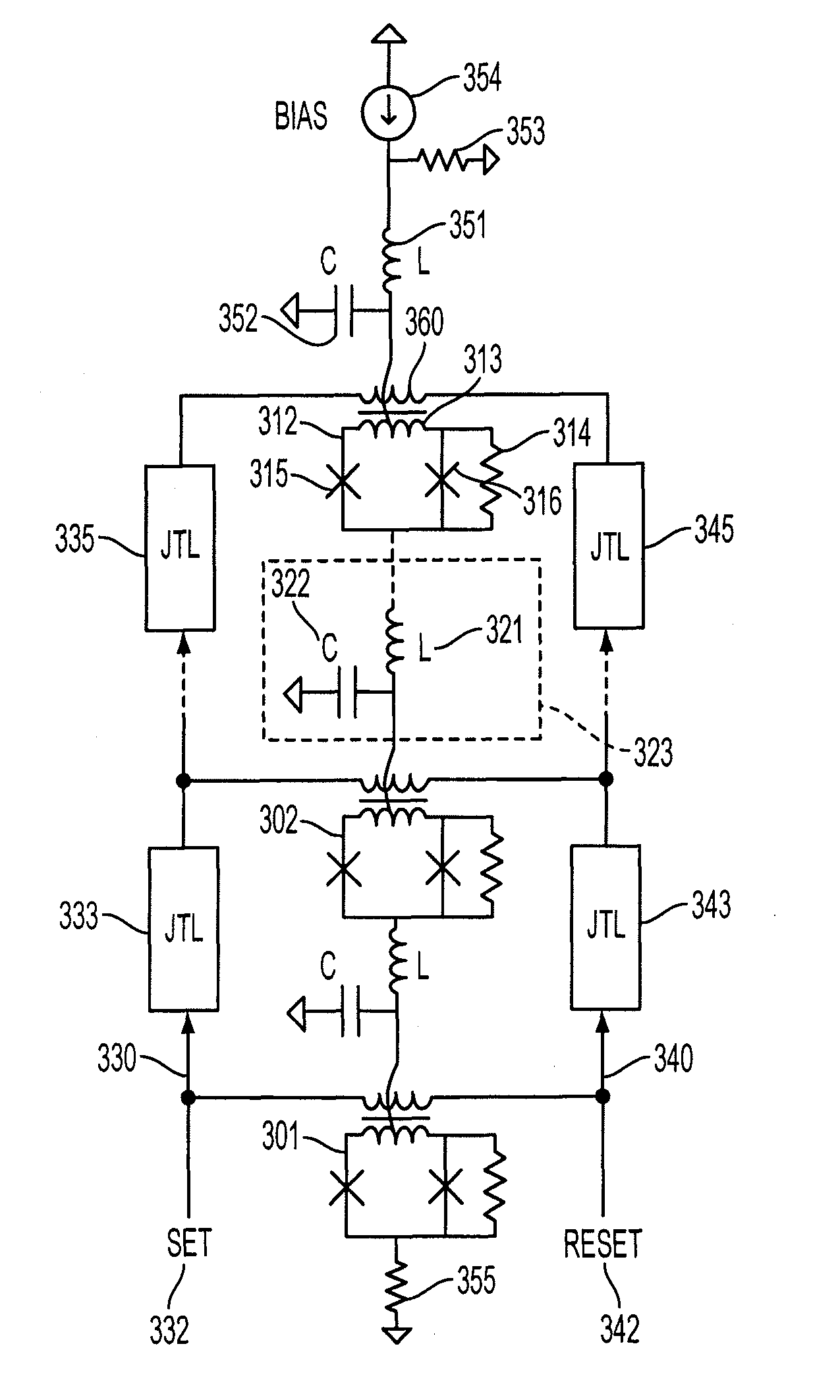
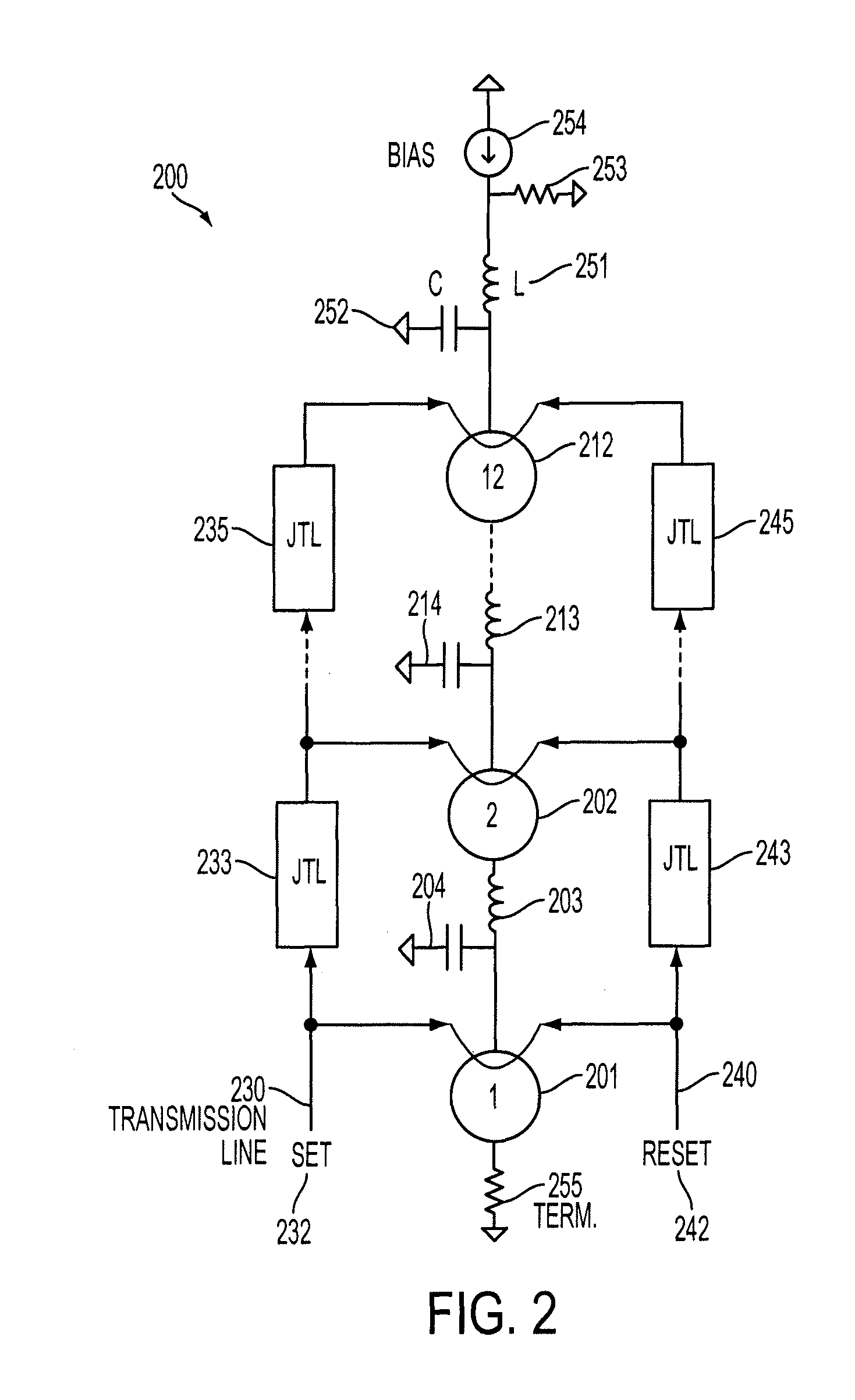
[0018]FIG. 2 schematically illustrates a distributed amplifier according to one embodiment of the disclosure. Circuit 200 of FIG. 2 illustrates a 12 stage amplifier represented by stages 1, 2 . . . 12. For brevity, only stages, 1, 2 and 12 are shown. Each stage is shown as having a voltage source. Thus, the first stage includes voltage source 201; the second stage is shown with voltage source 202. Amplification stage 12 is shown with voltage source 212. Each stage may optionally include a lumped resonant circuit connected to the voltage source. In FIG. 2, voltage source 202 is connected to inductor 203 and capacitor 204. Inductor 203 and capacitor 204 form a lumped resonant circuit. Similarly, voltage source 12 is connected to inductor 213 and capacitor 214.

[0019]FIG. 2 also shows bias 254 connected in parallel with resistor 253. In an exemplary application, termination resistor 255 was matched to resistor 253 and each was provided with 50Ω resistance. A lumped circuit comprising in...


PUM


Abstract

The disclosure generally relates to a method and apparatus for providing high-speed, low signal power amplification. In an exemplary embodiment, the disclosure relates to a method for providing a wideband amplification of a signal by forming a first transmission line in parallel with a second transmission line, each of the first transmission line and the second transmission line having a plurality of superconducting transmission elements, each transmission line having a transmission line delay; interposing a plurality of amplification stages between the first transmission line and the second transmission line, each amplification stage having an resonant circuit with a resonant circuit delay; and substantially matching the resonant circuit delay for at least one of the plurality of amplification stages with the transmission line delay of at least one of the superconducting transmission lines.

Description

BACKGROUND[0001]1. Field of the Invention[0002]The disclosure generally relates to wideband distributed amplifiers. More specifically, the disclosure relates to a method and apparatus for providing high-speed, low signal power amplification using superconducting technology.[0003]2. Description of Related Art[0004]A well-known wideband amplifier known as a distributed amplifier amplifies the incoming signal to an output signal commensurate with the desired amplification level. Distributed amplifier architecture introduces delay to achieve wideband characteristics. Conventional distributed amplifiers include a pair of transmission lines, each having a characteristic impedance, for independently connecting the inputs and outputs of several active devices.[0005]FIG. 1 shows the circuit diagram for a conventional distributed amplifier (“DA”). In FIG. 1, input signal 100 is directed to a first transmission line 110 having impedances ZI-1 to ZI-5. The amplified output signal 190 is provide...

Claims


Application Information

Patent Timeline
Patent Type & Authority Patents(United States)
IPC IPC(8): H03F3/60H03K19/195
CPCH03F19/00H03F3/605
Inventor HERRING, QUENTIN P.MILLER, DONALD LYNNPRZYBYSZ, JOHN XAVIER
Owner NORTHROP GRUMMAN SYST CORP
Why Eureka
Try Eureka