
Method and apparatus for irradiating laser

a laser and laser technology, applied in the direction of optical radiation measurement, semiconductor/solid-state device testing/measurement, instruments, etc., can solve the problems of reducing the grain size of the resultant polycrystalline-si film, preventing the improvement of the throughput of forming the polycrystalline-si film, and not achieving suitable grain size, etc., to achieve the effect of improving the throughput and g siz

Active Publication Date: 2010-05-25
NEC LCD TECH CORP
View PDF14 Cites 0 Cited by
  • Summary
  • Abstract
  • Description
  • Claims
  • Application Information

AI Technical Summary

Benefits of technology

[0011]It is therefore an exemplary object of the present invention to provide laser irradiation method and apparatus for crystallizing a semiconductor film, which is capable of providing a resultant film having a relatively large g size and improving the throughput therein.

Problems solved by technology

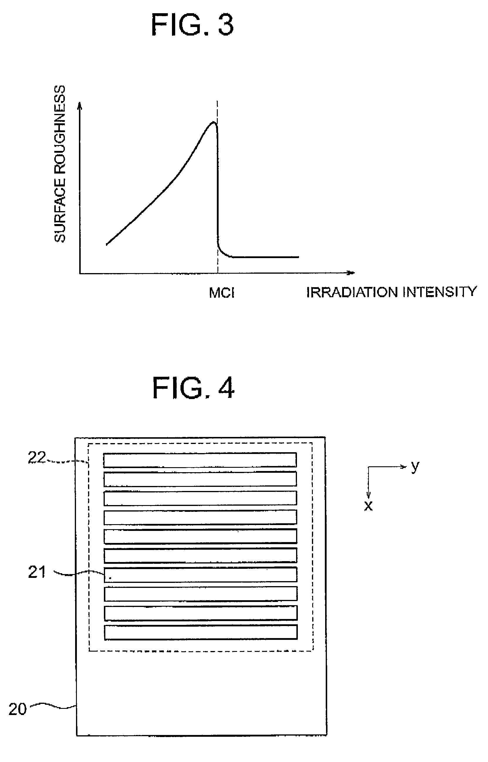
That is, when the irradiation intensity of the laser exceeds the microcrystallization intensity, the grain size of the resultant polycrystalline-Si film extremely reduces, whereby a suitable grain size is not achieved.
This impedes improvement in throughput of forming the polycrystalline-Si film.

Method used


Image

  • Method and apparatus for irradiating laser
  • Method and apparatus for irradiating laser
  • Method and apparatus for irradiating laser

Examples


first embodiment

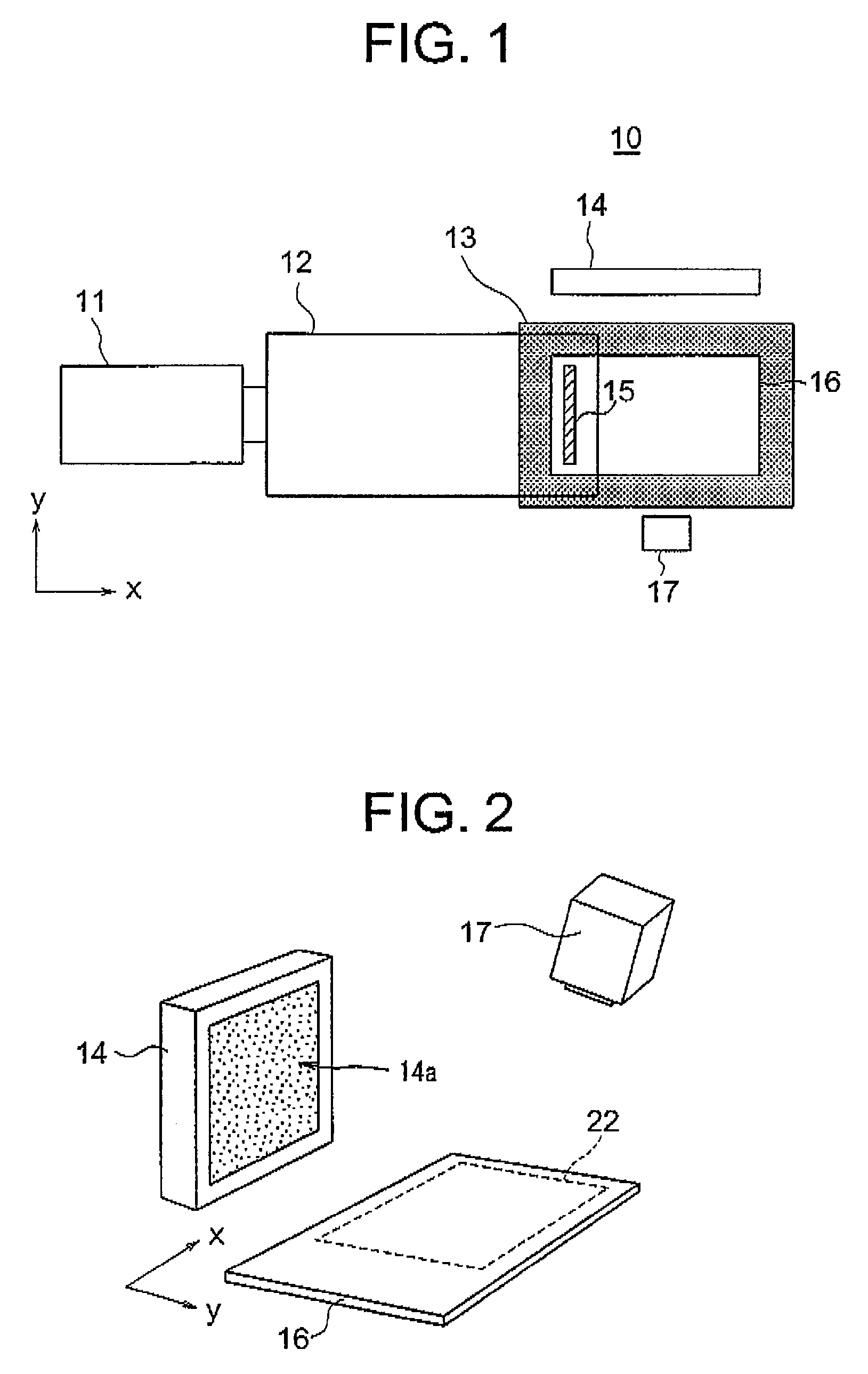
[0027]FIG. 1 is a top plan view showing the configuration of a laser irradiation apparatus, generally designated by numeral 10, for use in a laser irradiation method according to the present invention. The laser irradiation apparatus 10 includes a laser source 11, an optical system 12, a stage 13, a surface-light source unit 14 and an optical sensor configured by a charge coupled device 17. The laser irradiation apparatus 10 is used for melting and recrystallizing an amorphous-Si film formed on a surface of a substrate 16 to form a polycrystalline-Si film therefrom.

[0028]The laser source 11, which is an excimer laser device, generates a pulse laser having a predetermined lasing frequency toward the direction denoted by “x”. The optical system 12 forms the laser 15 irradiated from the, laser source 11 into an elongated rectangular shape, or linear shape, extending along the direction denoted by “y”. The substrate 16 is placed on the stage 13, and the rectangular-shaped laser is irrad...

second embodiment

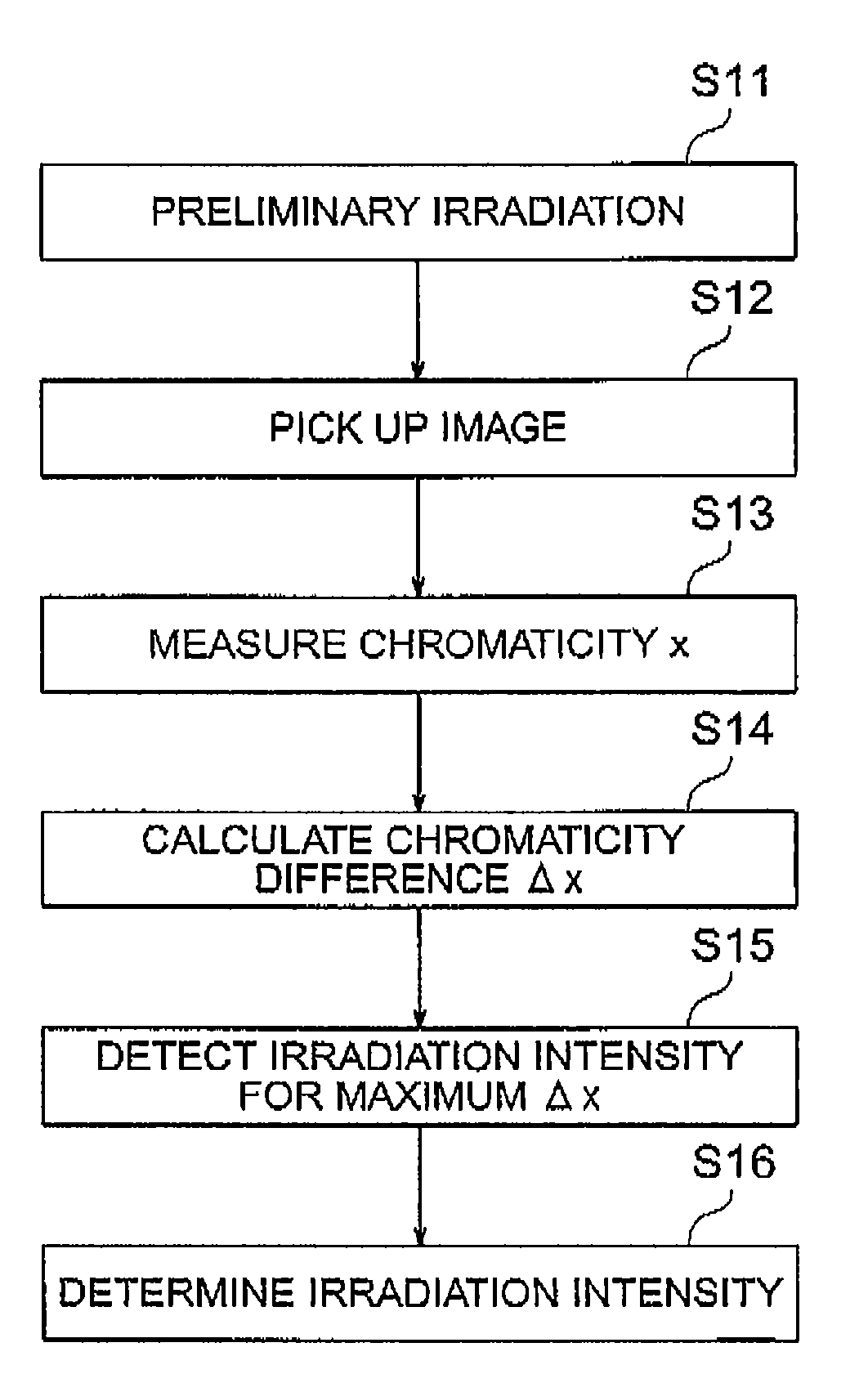
[0039]FIG. 7 is a flowchart showing the procedure of a method for judging the size uniformity in a laser irradiation process according to the present invention, In the method of the present embodiment, judged is the uniformity of the grain size of the polycrystalline-Si film formed by a laser irradiation. First, the laser irradiation apparatus shown in FIG. 1 is used, where the substrate for a product is placed on the stage 13, and the actual irradiation is performed to form a polycrystalline-Si film of the TFT devices (step S21). To form the polycrystalline-Si film, the irradiation intensity of laser is set lower than the microcrystallization intensity.

[0040]Next, while allowing the surface-light source unit 14 to illuminate the target irradiation area which has been irradiated by laser, the charge coupled device 17 picks-up the image of the target irradiation area in block (step S22). A plurality of judgment regions are set within the target irradiation area, and the chromaticity ...


PUM


Abstract

A laser irradiation process includes: scanning a substrate with laser having a predetermined lasing frequency at different irradiation intensities to form a plurality of first irradiation areas corresponding to the irradiation intensities; illuminating the first irradiation areas to reflected light receive from the fist irradiation areas; determining microcrystallization intensity based on the received reflected light; and determining irradiation intensity based on the thus determined microcrystallization intensity. The laser irradiation process uses the irradiation intensity for irradiating a polycrystalline film in a product semiconductor device.

Description

[0001]This application is based upon and claims the benefit of priority from Japanese patent application No. 2006-115710, filed on Apr. 19, 2006, the disclosure of which is incorporated herein in its entirety by reference.BACKGROUND OF THE INVENTION[0002]1. Field of the Invention[0003]The present invention relates to a method and apparatus for irradiating laser and, more particularly, to the technique such as used in a laser annealing process performed for forming g a polycrystalline thin film by irradiating a semiconductor thin film with a laser.[0004]2. Description of the Related Art[0005]A polycrystalline silicon thin film (referred to as polycrystalline-Si film hereinafter) is adopted as a conductive film of a thin-film-transistor (TFT) device formed on a glass substrate because of the easiness for processing. Generally, an excimer laser annealing (ELA) technique is employed to form the polycrystalline-Si film. In the ELA process, an amorphous silicon in film (referred to as amo...

Claims


Application Information

Patent Timeline
Patent Type & Authority Patents(United States)
IPC IPC(8): G01B11/00G01B11/28G01J3/46
CPCG01N21/8422H01L27/1296H01L27/1285H01L21/2026H01L21/02686H01L21/02422H01L21/02488H01L21/02678H01L21/02532H01L21/02691H01L21/02675
Inventor NAKATA, MITSURUSHIMAMOTO, HIROFUMIKANOH, HIROSHI
Owner NEC LCD TECH CORP
Learn More