Vehicle auxiliary electric-power-supplying system

a technology of vehicle, which is applied in emergency power supply arrangements, cable arrangements between relatively moving parts, electric devices, etc., can solve the problems of affecting the frequency of use of the inability to obtain electric power inverters, and the inability to operate the entire vehicle auxiliary electric power supply system. to achieve the effect of suppressing the frequency in us

Inactive Publication Date: 2010-06-01
MITSUBISHI ELECTRIC CORP
View PDF18 Cites 10 Cited by
  • Summary
  • Abstract
  • Description
  • Claims
  • Application Information

AI Technical Summary

Benefits of technology

[0007]A vehicle auxiliary electric-power-supplying system according to the present invention includes: an electric power inverter for converting a first type of dc power received through an overhead wire to a second type of dc power, and supplying the second type of dc power to a dc load; an electric power supplier for converting the first type of dc power received through the overhead wire to a third type of dc power; a power-outputting unit, connected to both the electric power inverter and the electric power supplier, for outputting either the second type of dc power or the third type of dc power; and a controller for receiving power from the power-outputting unit, and controlling the electric power inverter; therefore, the system can suppress the frequency in use for the power supplier as low as possible, and can normally stop-the electric power inverter by the power supplier being immediately started to supply electric power to a controller, even in a case in which normal electric power has become unable to be obtained from the output of the electric power inverter.

Problems solved by technology

However, when voltage of the back-up battery decreases and does not reach enough voltage to operate the controller, the controller does not start to operate, resultantly the entire vehicle-auxiliary-electric-power-supplying- system does not operate.
However, in the above described vehicle auxiliary electric-power-supplying system, there has been the following problem.
However, because normal electric power from the electric power inverter cannot be obtained due to short-circuit, and in addition, the power supplier is also stopped, the power for the controller is stopped; consequently, a normally stopping operation of the electric power inverter based on the command from the controller has been impossible.

Method used


Image

  • Vehicle auxiliary electric-power-supplying system
  • Vehicle auxiliary electric-power-supplying system
  • Vehicle auxiliary electric-power-supplying system

Examples


embodiment 1

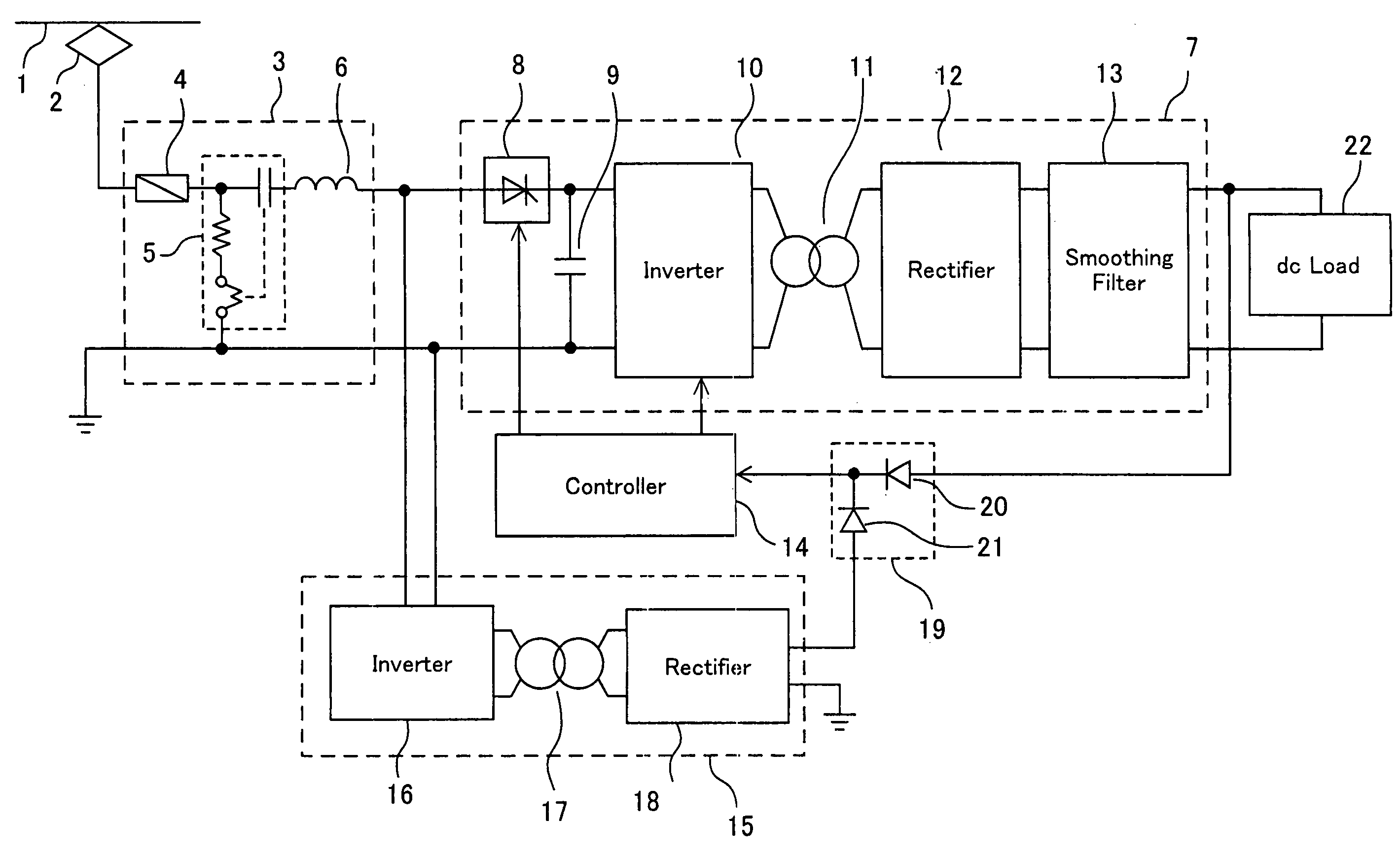
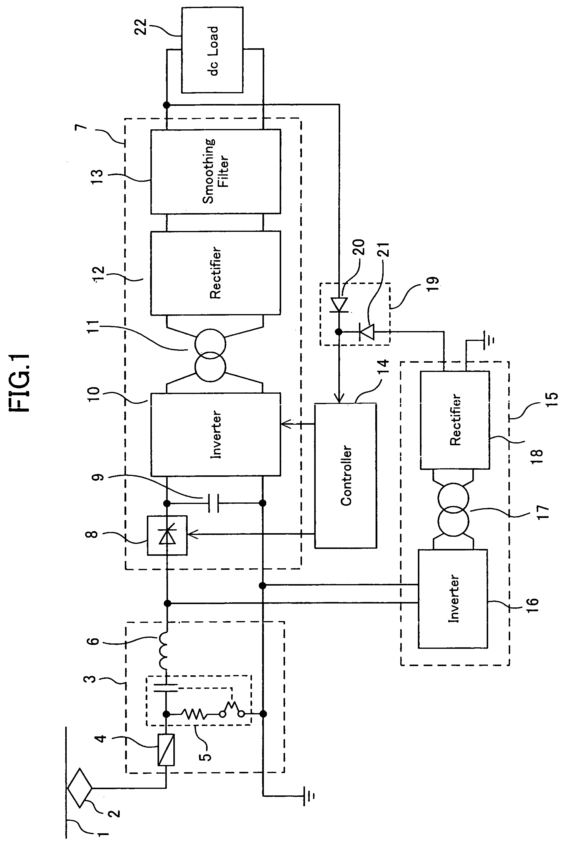
[0012]FIG. 1 is a view illustrating a configuration of a vehicle auxiliary electric-power-supplying system according to Embodiment 1 of the present invention. In this figure, numeral 1 denotes an overhead wire, and numeral 2 denotes a pantograph; here, high-voltage power from the overhead wire 1 is supplied to the vehicle auxiliary electric-power-supplying system through the pantograph 2. As the overhead wire 1, a wire placed above ground or in a third rail of subway systems is quoted as the example.

[0013]The configuration in the vehicle auxiliary electric-power-supplying system is explained. Numeral 3 denotes an automatic starter, which is composed of a fuse 4, an electromagnetic contactor 5, and an input filter reactor 6. In the electromagnetic contactor 5, a coil, a switch, and a resistor for decreasing voltage are represented. In addition, a contactor, which is not illustrated, is provided between the resistor and the coil. A controller described later detects any excessive volt...

embodiment 2

[0032]Although the vehicle auxiliary electric-power-supplying system in which only the dc electric power is outputted has been explained in Embodiment 1, a vehicle auxiliary electric-power-supplying system in which both ac electric power and dc electric power are outputted is explained in Embodiment 2.

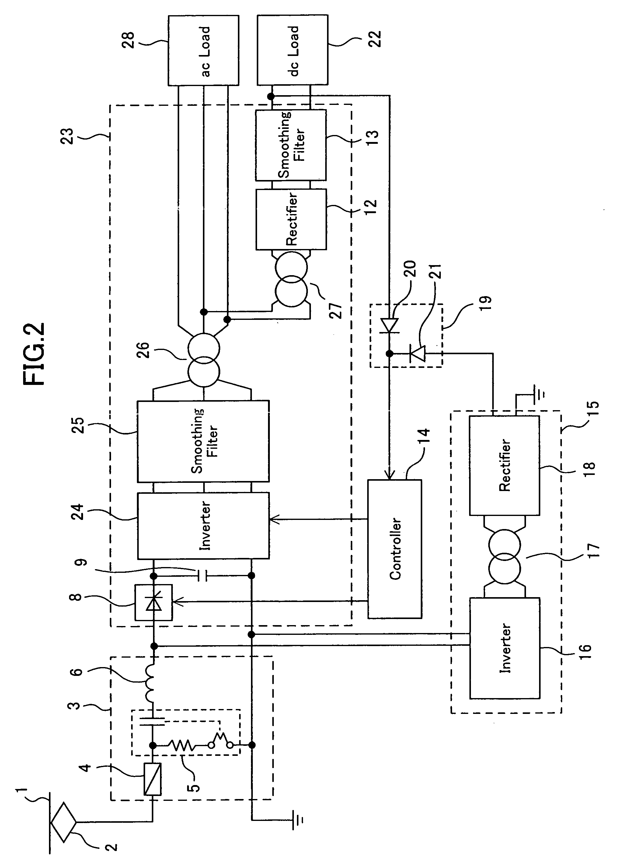
[0033]FIG. 2 is a view illustrating a configuration of the vehicle auxiliary electric-power-supplying system according to Embodiment 2.

[0034]In this figure, numeral 23 denotes an electric power inverter, numeral 24 denotes an inverter, numeral 25 denotes a smoothing filter, numerals 26 and 27 denote transformers, and numeral 28 denotes an ac load. The ac load 28 includes an air conditioner. Other numerals are the same elements as those represented in Embodiment 1.

[0035]Similarly to the case in Embodiment 1, when high-voltage dc power is supplied to the inverter 24, the power is converted into high-voltage ac power in the inverter 24. Although the inverter 24 is used for converting dc i...

embodiment 3

[0040]FIG. 3 is a view illustrating a vehicle auxiliary electric-power-supplying system according to Embodiment 3 of the present invention. In this figure, numeral 29 denotes an automatic starter having a fuse 30. Numeral 31 denotes an electric power inverter, numeral 32 denotes an electromagnetic contactor, numeral 33 denotes an input filter reactor, and numeral 35 denotes a controller. Other numerals are the same as those represented in Embodiment 1.

[0041]In the vehicle auxiliary electric-power-supplying system according to Embodiments 1 and 2, the electromagnetic contactor 5 has been automatically started to operate using a resistor that can decrease the voltage until the system can start to operate; however, in some areas, because the voltage of the overhead wire 1 is so high that there may be cases in which an electromagnetic contactor having voltage-resistant. characteristics for enabling automatic start is not available, or the vehicle auxiliary electric-power-supplying syste...


PUM


Abstract

A vehicle auxiliary electric-power-supplying system can normally stop an electric power inverter by the frequency in use for an electric power supplier being suppressed as low as possible, and electric power being immediately started to be supplied from the power supplier to a controller in a case in which normal electric power has become unable to be obtained from power-outputting of the electric power inverter. The system includes: the electric power inverter for converting a first type of dc power received through an overhead wire to a second type of dc power, and supplying the second type of dc power to a dc load; the power supplier for converting the first type of dc power received through the overhead wire to a third type of dc power; a power-outputting unit, connected to both the electric power inverter and the electric power supplier, for outputting either the second type of dc power or the third type of dc power; and the controller for receiving power from the power-outputting unit, and controlling the electric power inverter.

Description

[0001]This disclosure is based up on International Application No. PCT / JP2004 / 000829, filed Jan. 29, 2004, the contents of which are incorporated by reference.TECHNICAL FIELD[0002]The present invention relates to vehicle auxiliary electric-power-supplying systems that supply low-voltage power, which is converted from high-voltage power, to loads such as an air conditioner and lighting fixtures installed in an electric vehicle.BACKGROUND ART[0003]Generally, an electric vehicle has a back-up battery therein. Moreover, a vehicle is provided therein with a vehicle auxiliary electric-power-supplying system that converts high-voltage power supplied from an overhead wire, to low-voltage power, and supplies the low-voltage power to a load installed in the vehicle. Only when electric power has been supplied from the back-up battery voltage to a controller of the vehicle auxiliary electric-power-supplying system, and the controller has operated, the entire vehicle auxiliary electric-power-sup...

Claims


Application Information

Patent Timeline
Patent Type & Authority Patents(United States)
IPC IPC(8): B60L1/00H02J1/00B60L1/02B60L1/14B60L5/00B60M1/02H02J1/10H02J9/06H02M3/22
CPCB60L1/00B60L1/02B60L1/10B60L1/14B60L2200/26H02J1/10H02M2001/0006Y02T10/725B60L2210/20H02M1/0006Y02T10/72
Inventor KUSUBAYASHI, CHIYO
Owner MITSUBISHI ELECTRIC CORP
Why Eureka
Try Eureka