
Battery management system and driving method thereof

a battery management system and battery technology, applied in secondary cell servicing/maintenance, safety/protection circuits, instruments, etc., can solve the problems of increased cost, difficult to determine abnormalities in the circuits of the battery voltage detecting unit, and serious air pollution, and achieve the effect of simple structur

Inactive Publication Date: 2010-06-01
SAMSUNG SDI CO LTD
View PDF8 Cites 11 Cited by
  • Summary
  • Abstract
  • Description
  • Claims
  • Application Information

AI Technical Summary

Benefits of technology

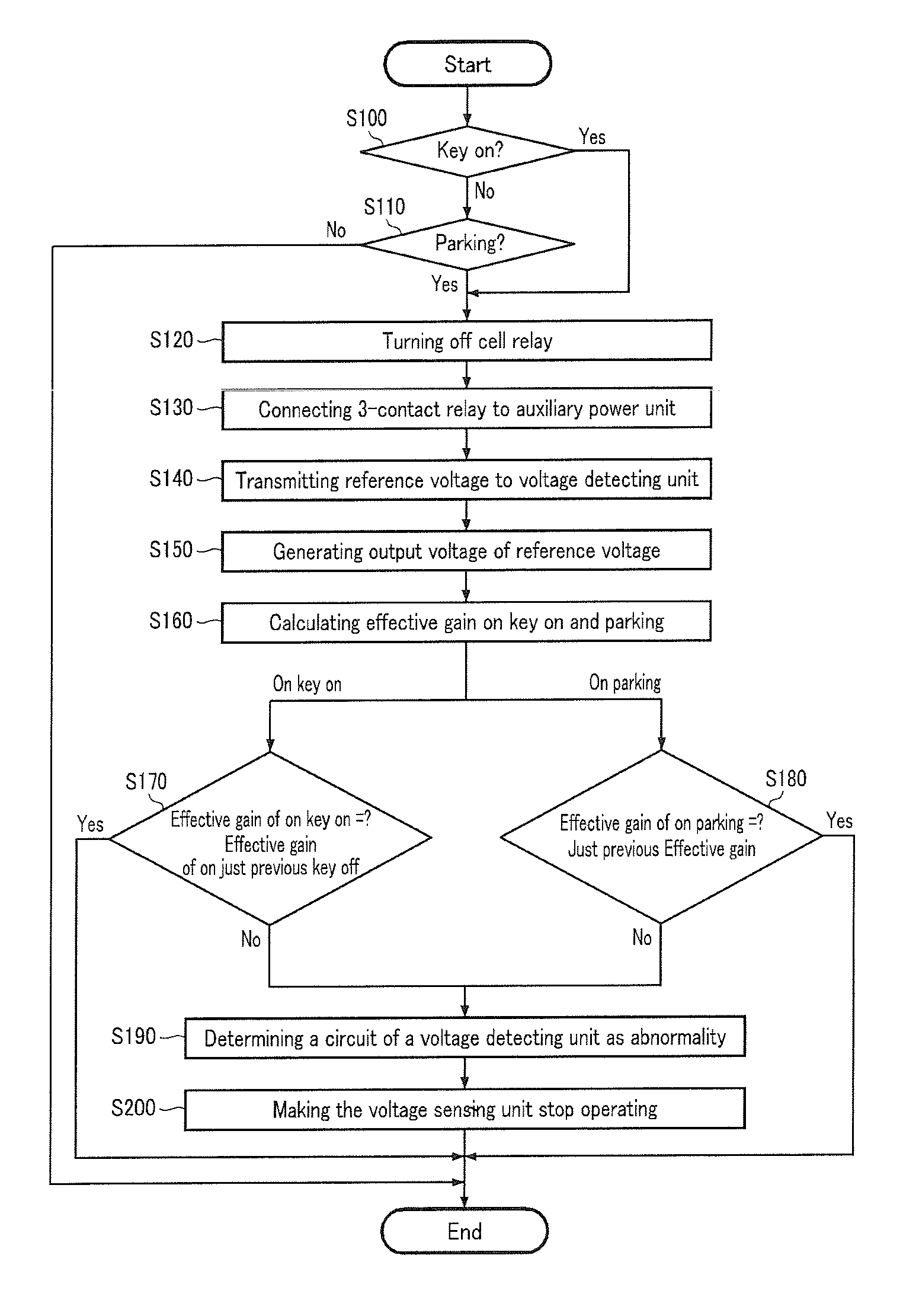
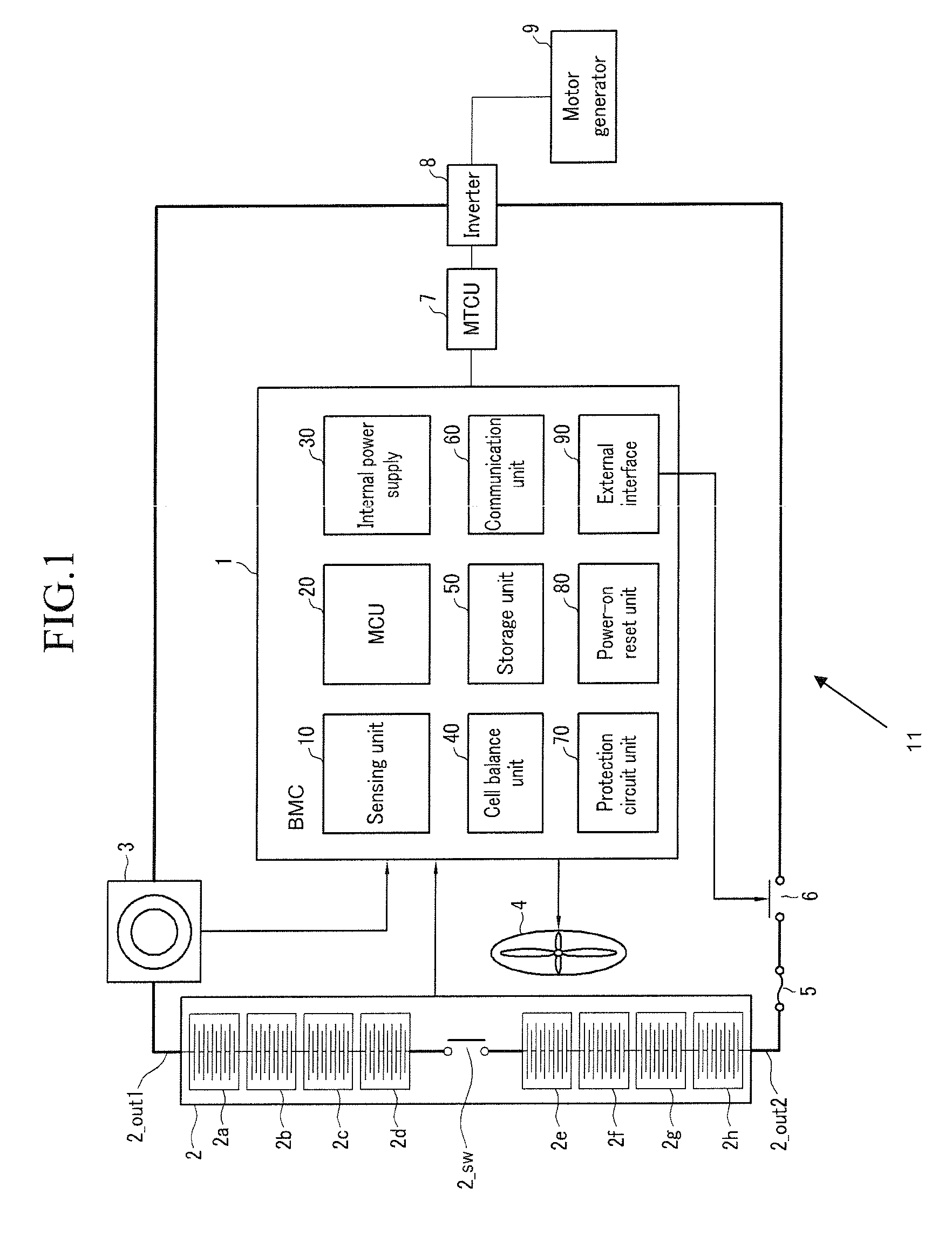
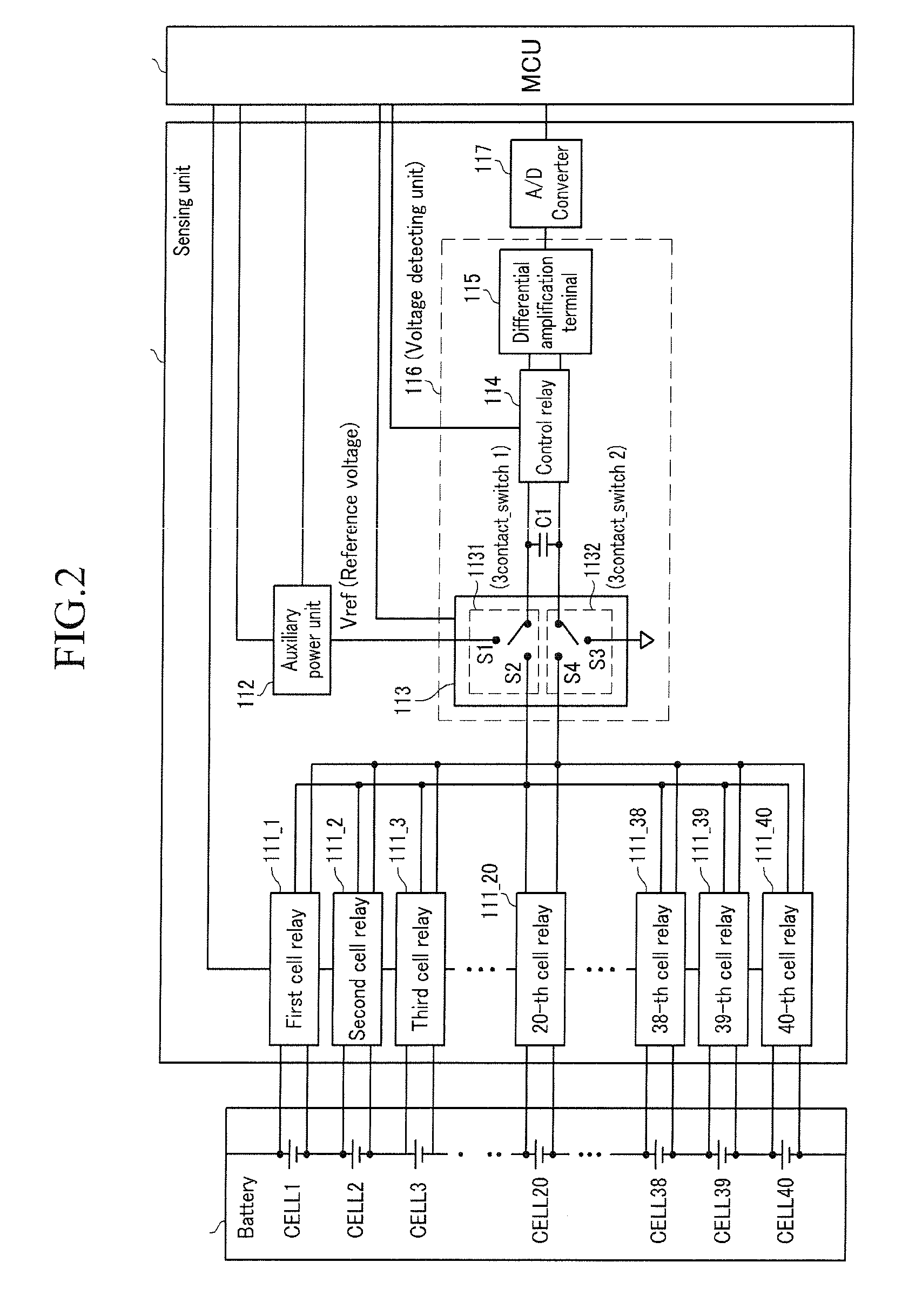
The present invention provides a battery management system and method for a hybrid vehicle that can detect abnormalities in the battery voltage detection circuit. The system includes a plurality of cells, a first cell relay among the cell relays, a 3-contact relay, a voltage detecting unit, and an MCU. The voltage detecting unit receives a first voltage through the 3-contact relay and generates a second voltage. The MCU calculates an effective gain based on the ratio of the second voltage to the input voltage. The system can compare the effective gain to a previous effective gain or a reference voltage transmitted through the 3-contact relay to determine if there is an abnormality in the circuit. The system can also include a capacitor to store the first voltage, a differential amplification terminal, and a control relay to connect the capacitor with the differential amplification terminal. The driving method of the battery management system involves transmitting the reference voltage to the voltage detecting unit and calculating the output voltage based on the reference voltage. The technical effects of the invention include improved battery management and detection of abnormalities in the battery voltage detection circuit.

Problems solved by technology

Vehicles using a gasoline or diesel oil internal combustion engines have caused serious air pollution.
Accordingly, when the battery voltage is detected using a conventional battery voltage detecting unit, there are problems in that the cost thereof is increased.
It is also difficult to determine abnormalities in the circuits of the battery voltage detecting unit, because of small current leakages generated from the voltage detecting unit cell couplings, respectively coupled to the battery cells, and the overall complexity of the circuit structure.

Method used


Image

  • Battery management system and driving method thereof
  • Battery management system and driving method thereof
  • Battery management system and driving method thereof

Examples


Embodiment Construction

[0026]Reference will now be made in detail to the present embodiments of the present invention, examples of which are illustrated in the accompanying drawings, wherein like reference numerals refer to the like elements throughout. The embodiments are described below in order to explain the present invention by referring to the figures.

[0027]In the following detailed description, only certain exemplary embodiments of the present invention have been shown and described, simply by way of illustration. As those skilled in the art would realize, the described embodiments may be modified in various different ways, all without departing from the spirit or scope of the present invention. Accordingly, the drawings and description are to be regarded as illustrative in nature and not restrictive. Like reference numerals designate like elements throughout the specification.

[0028]Throughout this specification and the claims which follow, when it is described that an element is “coupled to” anoth...


PUM

PropertyMeasurementUnit
voltageaaaaaaaaaa
output voltageaaaaaaaaaa
input voltageaaaaaaaaaa

Abstract

A battery management system and a driving method thereof. The battery management system manages a plurality of battery cells, and a plurality of cell relays respectively coupled to the plurality of cells. The battery management system includes a voltage detecting unit and an MCU. The voltage detecting unit receives a first voltage corresponding to an input voltage transmitted through a 3-contact relay coupled to a first cell corresponding to the turn-on first cell relay when the first cell relay is turned on, and generating a second voltage corresponding to the first voltage. The MCU calculates an effective gain in correspondence with a ratio of the second voltage to the input voltage and controls a connection of the 3-contact relay.

Description

CROSS-REFERENCE TO RELATED APPLICATIONS[0001]This application claims the benefit of Korean Application No. 2006-86149, filed Sep. 7, 2006, in the Korean Intellectual Property Office Sep. 7, 2006, the disclosure of which is incorporated herein by reference.BACKGROUND OF THE INVENTION[0002]1. Field of the Invention[0003]Aspects of the present invention relate to a battery management system and a battery management method. More particularly, aspect of the present invention relate to a battery management system for a vehicle utilizing electrical energy.[0004]2. Description of the Related Art[0005]Vehicles using a gasoline or diesel oil internal combustion engines have caused serious air pollution. Accordingly, various efforts for developing electric or hybrid vehicles have recently been made to reduce air pollution.[0006]An electric vehicle uses an electric motor run by electrical energy output by a power source. Many electric vehicles use a battery formed by one battery pack comprising...

Claims


Application Information

Patent Timeline
Patent Type & Authority Patents(United States)
IPC IPC(8): G01N27/416
CPCB60L3/0038B60L3/12B60L11/1803B60L11/1855B60L11/1857B60L11/1861B60L11/1866B60L11/1868B60L11/1874H02J7/1423H02J7/1461H02J7/0014H02J7/0021B60L3/0046Y02T10/7055B60L2240/545B60L2240/547B60L2240/549Y02T10/7005Y02T10/7022Y02T10/7044Y02T10/7061Y02T10/7066B60L50/51B60L58/19B60L58/16B60L58/22B60L58/20B60L58/26B60L58/15B60L58/14Y02T10/70Y02E60/10H02J7/0013H02J7/0047H02J7/00308H02J7/00304H01M10/44H02J7/00B60L50/50
Inventor TAE, YONG-JUNCHOI, SOO-SEOKLEE, YOUNG-JOYUN, HAN-SEOKSEO, SE-WOOKLIM, GYE-JONGKIM, BEOM-GYUPARK, HO-YOUNG
Owner SAMSUNG SDI CO LTD
Learn More