Loop antenna with a parasitic radiator

a loop antenna and radiator technology, applied in the field of loop antennas, can solve the problems of too weak increase the size of the antenna system, and the distance longer, and achieve the effect of low radiation efficiency of the loop antenna and boost performan

Active Publication Date: 2010-06-01
NOKIA TECHNOLOGLES OY
View PDF34 Cites 39 Cited by
  • Summary
  • Abstract
  • Description
  • Claims
  • Application Information

AI Technical Summary

Benefits of technology

[0008]It is an objective of the present invention to provide an antenna construction that allows the thickness of an antenna structure be smaller than that of planar antennas according to prior art without sacrificing the radiation efficiency at the desired RF-bands as 900 MHz GSM and 1800 MHz / 1900 MHz DCS / PCS. A further object of the invention is to provide an antenna construction that is less sensitive to changes in positions of electrically conductive objects in the vicinity, e.g. to opening position of a folding phone, than planar antennas according to prior art. It also an object of the invention provide a mobile communication device having an antenna structure that is inside a cover part of said mobile communication device so that the thickness of an antenna structure can be smaller than that of planar antennas according to prior art without sacrificing the radiation efficiency at the desired RF-bands as 900 MHz GSM and 1800 MHz / 1900 MHz DCS / PCS.
[0009]The objectives of the invention are achieved by a loop antenna structure equipped with an electrically conductive parasitic radiator. From a viewpoint of transmitting operation the electrically conductive parasitic radiator receives RF-electromagnetic energy from the antenna loop via an mutual electromagnetic coupling between the antenna loop and the parasitic radiator over an electrically insulating area and emits a part of the received electromagnetic energy in a form of RF-electromagnetic radiation to the surrounding space. From a viewpoint of receiving operation the electrically conductive parasitic radiator captures RF-electromagnetic energy from RF-electromagnetic radiation falling to the parasitic radiator and transfers a part of the captured RF-electromagnetic energy to the antenna loop via the mutual electromagnetic coupling. The problem associated with low radiation efficiency of a loop antenna at 1800 MHz / 1900 MHz DCS / PCS bands is solved with the aid of the parasitic radiator that boosts performance at those frequency bands.
[0016]The invention improves the radiation efficiency of a loop antenna at 1800 MHz / 1900 MHz DCS / PCS. This is an important improvement for loop antennas normally having low efficiency at the high frequency bands.
[0017]The solution of the invention allows the thickness of an antenna to be reduced without compromising the radiation efficiency at the desired RF-bands as 900 MHz GSM and 1800 MHz / 1900 MHz DCS / PCS.
[0018]The solution of the invention reduces the sensitivity of the radiating efficiency at a desired frequency band to existence of electrically conductive materials in the vicinity. This is an important property for example in a folding phone application in which electromagnetic properties of the near-surroundings of an antenna depends in some extent on an opening position of a phone mechanics.
[0019]The solution of the invention allows reducing the size of the antenna loop thus contributing to a miniaturization of the antenna.

Problems solved by technology

The upper limit of the distance comes from the fact that a too long a distance would make the electromagnetic coupling between the parasitic radiator and the antenna loop too weak and, naturally, making the distance longer increases the size of an antenna system.

Method used


Image

  • Loop antenna with a parasitic radiator
  • Loop antenna with a parasitic radiator
  • Loop antenna with a parasitic radiator

Examples


example a

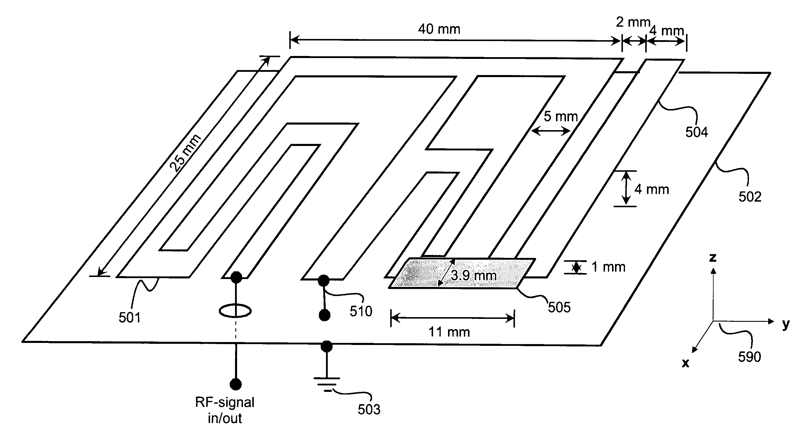
[0049 in FIG. 7 shows an exemplary embodiment of the invention in which characteristics of an antenna structure are affected by using a coupling element 705 between an antenna loop 701 and a parasitic radiator 702. A coupling element 705 may comprise active and / or passive electrical components. In a general case, there can be one or more coupling elements. In example B the coupling element is a low-impedance galvanic contact 704. In example C the coupling element is a capacitor 706 with the aid of which the coupling between the antenna loop and the parasitic radiator can be made to have a strong capacitive nature. In example D there is an active electrical component as the coupling element. A capacitance diode 707 acts as the coupling element and its small-signal capacitance value is controlled with a dc-bias voltage Ubias fed via ac-decoupling coils 708 and 709.

[0050]FIG. 8 shows an exemplary embodiment of the invention in which there are two parasitic radiators 802 and 803 and two...


PUM


Abstract

It is an objective of the present invention to provide an antenna construction that allows the thickness of an antenna structure be lower than that of planar antennas according to prior art without sacrificing the radiation efficiency at the desired RF-bands as 900 MHz GSM and 1800 MHz / 1900 MHz DCS / PCS. A further object of the invention is to provide an antenna construction that is insensitive to changes in positions of electrically conductive objects in the vicinity. The objectives of the invention are achieved by a loop antenna structure equipped with an electrically conductive parasitic radiator that is electro-magnetically coupled with the antenna loop. Performance at the DCS / PCS bands can be further improved by using an electrically conductive tuner element that provides a stronger electromagnetic coupling between the antenna loop and the parasitic radiator.

Description

FIELD OF THE INVENTION[0001]The invention relates to antenna systems, and more particularly to loop antennas that can be used for example in personal mobile communication devices e.g. in a cellular mobile phone.BACKGROUND OF THE INVENTION[0002]Important technical properties of an antenna structure are physical size and radiation efficiency. For example, an antenna of a cellular mobile phone is nowadays usually located inside the cover of the phone device. Especially in folding mobile phones, e.g. in a clamshell type phone, the thickness of the antenna structure is an important quantity. This is due to the fact that a phone device should be thin enough also in a folded state. Another important issue is the radiation efficiency. The radiation efficiency means the ratio of the power supplied to an antenna to the power radiated by the antenna. Small radiation efficiency means increased power consumption when a desired level of radiated power is generated. The power consumption is a cruc...

Claims


Application Information

Patent Timeline
Patent Type & Authority Patents(United States)
IPC IPC(8): H01Q7/00
CPCH01Q1/243H01Q7/00H01Q9/0421H01Q9/0442H01Q5/385H01Q5/321H01Q5/371H01Q5/378H01Q9/265
Inventor OZDEN, SINASI
Owner NOKIA TECHNOLOGLES OY
Why Eureka
Try Eureka