Wireless position sensor

a position sensor and wireless technology, applied in the field of wireless position sensors, can solve the problem of limited time for insertion of devices

Active Publication Date: 2010-06-01
BIOSENSE
View PDF31 Cites 1161 Cited by
  • Summary
  • Abstract
  • Description
  • Claims
  • Application Information

AI Technical Summary

Benefits of technology

[0021]It is an object of some aspects of the present invention to provide improved apparatus and methods for real-time determination of the location and orientation of intrabody objects.

Problems solved by technology

In many instances, insertion of a device is for a limited time, such as during surgery or catheterization.

Method used


Image

  • Wireless position sensor
  • Wireless position sensor
  • Wireless position sensor

Examples


Embodiment Construction

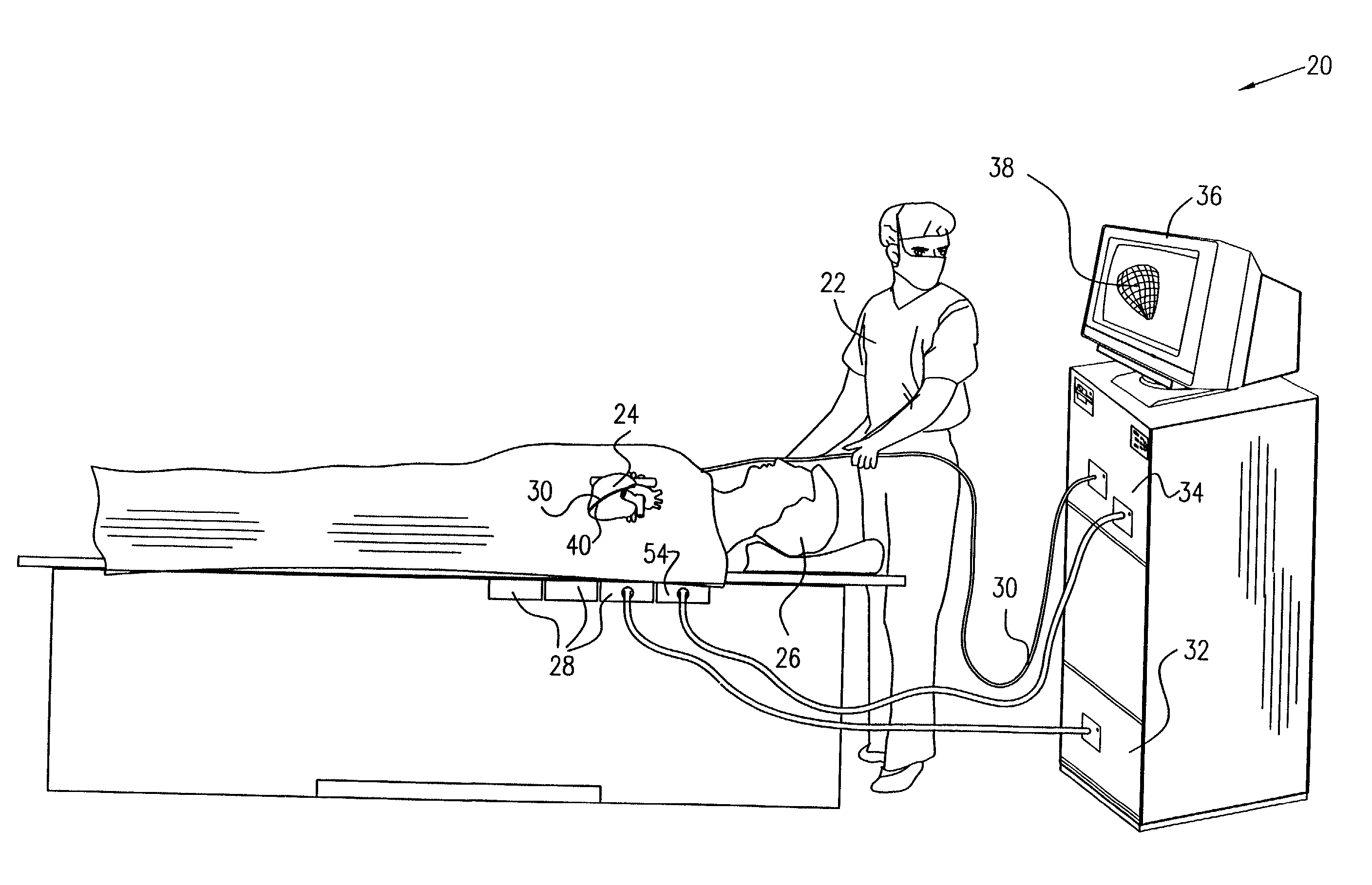
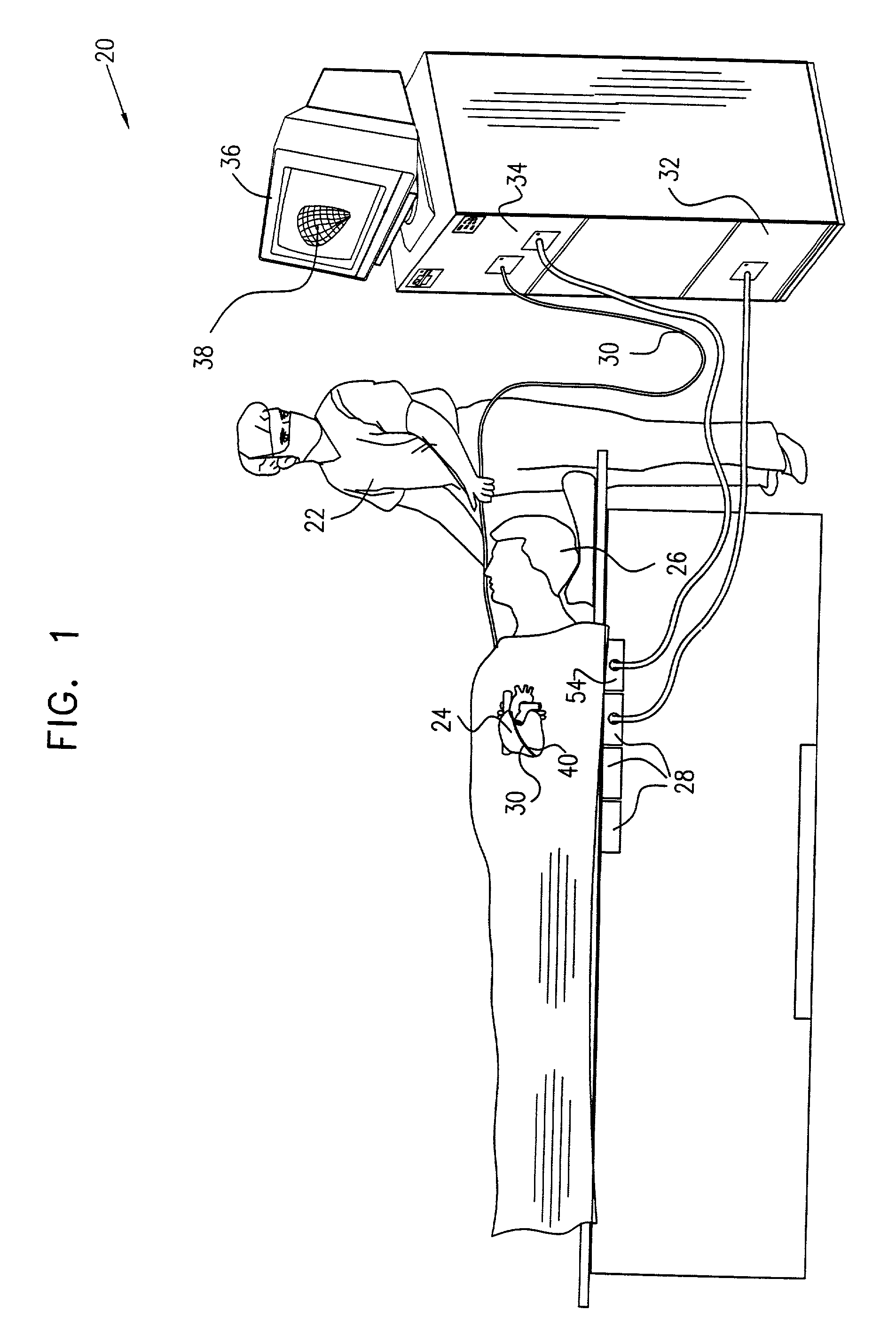
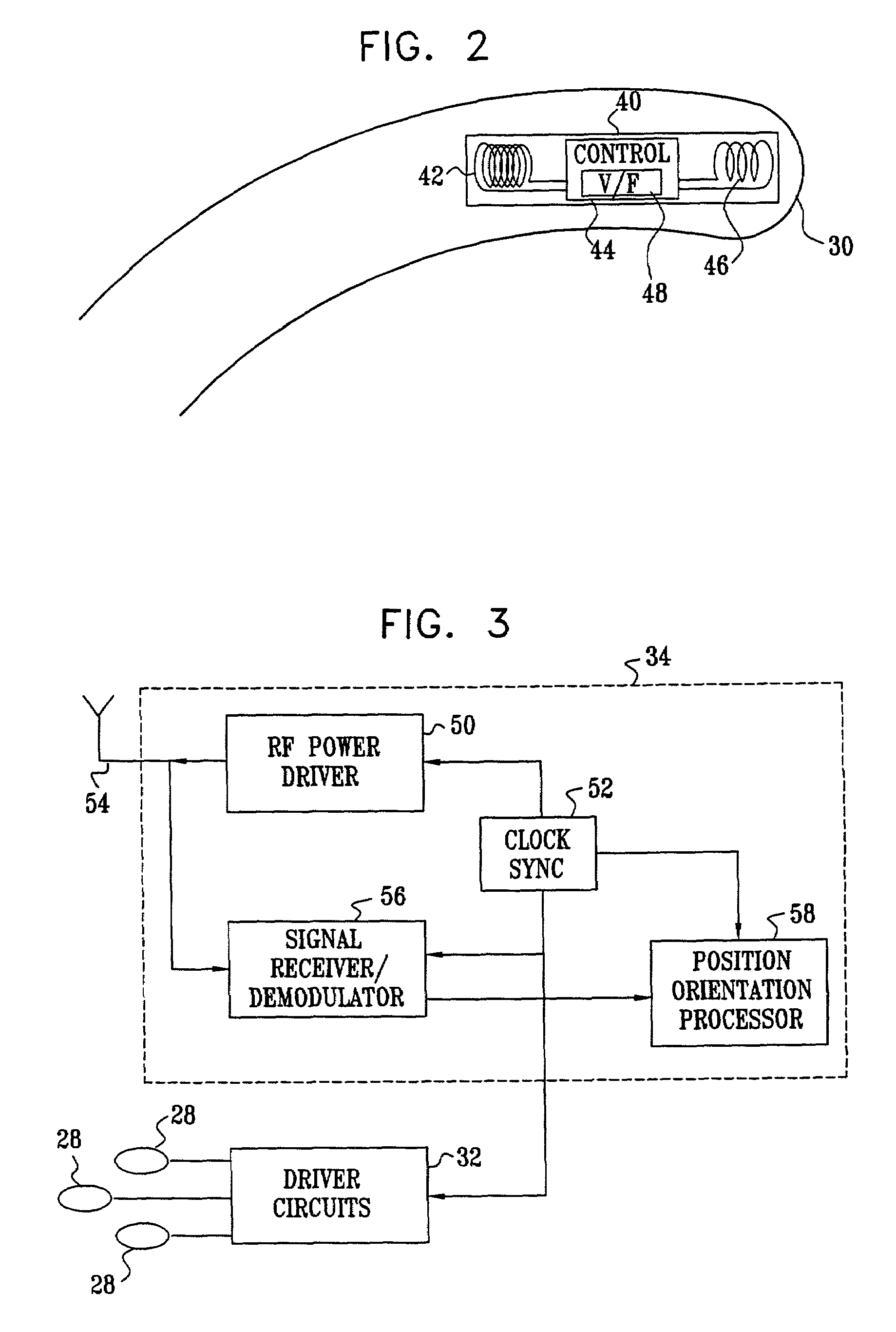
[0117]FIG. 1 is a schematic, pictorial illustration of a mapping system 20, for mapping a heart 24 of a subject 26, in accordance with a preferred embodiment of the present invention. System 20 comprises an elongate probe, preferably a catheter 30, which is inserted by a user 22 through a vein or artery of the subject into a chamber of the heart. Catheter 30 comprises a wireless position transponder 40, preferably near the distal tip of the catheter. Transponder 40 is shown in detail in FIG. 2. Optionally, catheter 30 comprises two or more transponders of this sort, mutually spaced along the length of the catheter, in order to give position and orientation coordinates at multiple points along the catheter.

[0118]To operate transponder 40, subject 26 is placed in a magnetic field generated, for example, by situating under the subject a pad containing field generator coils 28 for generating a magnetic field. Coils 28 are driven by driver circuits 32 to generate electromagnetic fields a...


PUM


Abstract

Apparatus for tracking an object includes a plurality of field generators, which generate electromagnetic fields at different, respective frequencies in a vicinity of the object, and a radio frequency (RF) driver, which radiates a RF driving field toward the object. A wireless transponder is fixed to the object. The transponder includes at least one sensor coil, in which a signal current flows responsive to the electromagnetic fields, and a power coil, which receives the RF driving field and conveys electrical energy from the driving field to power the transponder. The power coil also transmits an output signal responsive to the signal current to a signal receiver, which processes the signal to determine coordinates of the object.

Description

FIELD OF THE INVENTION[0001]The present invention relates generally to intrabody tracking systems, and specifically to wireless methods and devices for tracking the position and orientation of an object in the body.BACKGROUND OF THE INVENTION[0002]Many surgical, diagnostic, therapeutic and prophylactic medical procedures require the placement of objects such as sensors, treatment units, tubes, catheters, implants and other devices within the body. These procedures cover a large spectrum including, for example:[0003]insertion of electrodes for therapeutic or diagnostic purposes,[0004]placement of tubes to facilitate the infusion of drugs, nutritional and other fluids into a patient's circulatory system or digestive system,[0005]insertion of probes or surgical devices to facilitate cardiac or other types of surgery, and[0006]biopsies or other diagnostic procedures.[0007]In many instances, insertion of a device is for a limited time, such as during surgery or catheterization. In other ...

Claims


Application Information

Patent Timeline
Patent Type & Authority Patents(United States)
IPC IPC(8): A61B5/05A61B5/00G01B7/00A61B5/06A61B19/00H04B1/59
CPCA61B5/0031A61B5/06A61B19/52A61B19/5244A61B2019/547A61B2019/5251A61B2019/5272A61B2019/5416A61B2019/448A61B90/36A61B2034/2072A61B2090/3916A61B34/20A61B90/98A61B2034/2051A61B2090/397A61B5/062
Inventor GOVARI, ASSAF
Owner BIOSENSE
Why Eureka
Try Eureka