Efficient use of NVRAM during takeover in a node cluster
Active Publication Date: 2010-06-01
NETWORK APPLIANCE INC
72 Cites 46 Cited by
AI-Extracted Technical Summary
Problems solved by technology
However, the protocol can “hang up” for hours without any timeout, which is detrimental.
In addition, since NFS is not found in most PC operating systems it is not widely used in filers that are accessed by PC clients.
This is clearly inefficient.
If there is a problem with the failed fi...
View moreMethod used
[0035]After the local filer has taken over the operations of its failed partner, and the partner's mirrored log information has been flushed from the local filer's NVRAM to hard disk, the WAFL section of the partner half of the NVRAM is used by the local filer to increase the size of its WAFL log capacity and thereby improve operation of the local filer during takeover. This operation is described in greater detail further in this detailed description.
[0036]FIG. 2 is a block diagram of filer 200 comprising a processor 202, a memory 204, a storage adapter 206 and at least one network adapter 208 all interconnected by a system bus 210, which is preferably a conventional peripheral computer interconnect (PCI) bus. Storage adapter 206 is connected to disks 216 via a Fibre Channel link. The filer also includes a storage operating system 230 stored in memory 204 that implements a file system to logically organize information stored as a hierarchical structure of directories and files on the disks in an assigned disk shelf 212. The filer also includes an NVRAM 214 and cluster interconnect 153. Disks in the disk shelf are typically organized as a RAID 4 (Redundant Arrays of Inexpensive Disks) array to protect against data loss caused by disk failure in a manner well known in the art. RAID arrays also improve data availability because a filer can continue operation even with a single failed hard disk. In the illustrative embodiment described herein, the operating system 230 is preferably the Data ONTAP™ storage operating system 300 available from Network Appliance, Inc. that implements a Write Anywhere File Layout (WAFL) file system on the RAID 4 array.
[0043]In an alternate embodiment of the invention, some functions performed by the storage operating system may be implemented as logic circuitry embodied within a field programmable gate array (FPGA) or an application specific integrated circuit (ASIC). This type of hardware implementation increases the performance of the file service provided by a filer in response to a file system request issued by a client 110. Moreover, in another alternate embodiment of the invention, the processing elements of network and storage adapters may be conf...
View moreBenefits of technology
[0017]The present invention provides a technique for increasing the storage capacity of an NVRAM during a takeover operation, thereby enhancing the performance of a local filer when processing requests directed to a failed partner filer of a cluster. The NVRAM to is organized into two halves or segments: a local half configured to store file system information directed to the local filer, and a partner half for storing such information directed to the partner filer.
[0018]After the local filer takes over file service operations from the failed partner, the information stored in the partner half of the NVRAM is flushed to hard disk. According to the teaching of the invention, the partner half of the NVRAM is then used to provide additional NVRAM storage capacity for file system information processed during takeover. The additional capacity effectively doubles the size of the NVRAM allocated for temporary storage of processed file system information.
[0019]Specifically, each half of the NVRAM comprises a plurality of sections, including a file system (e.g. WAFL) section. The WAFL section in the local h...
View moreAbstract
A server storage system operating in a cluster mode, and a method for operating the server system that provides additional memory for use by a non-failed server to store log records while taking over the operations of a failed server.
Application Domain
Technology Topic
Image
Examples
- Experimental program(1)
Example
[0027]The inventive technique described herein may apply to any type of special-purpose (e.g., server) or general-purpose computer, including a standalone computer or portion thereof, embodied as or including a storage system. Moreover, the teachings of this invention can be adapted to a variety of storage system architectures including, but not limited to, a network-attached storage environment, a storage area network and disk assembly directly-attached to a client or host computer. The term “storage system” should therefore be taken broadly to include such arrangements in addition to any subsystems configured to perform a storage function and associated with other equipment or systems. It is expressly contemplated that the various processes, architectures and procedures described herein can be implemented in hardware, firmware or software, including a computer-readable medium having stored thereon program instructions that perform a series of steps.
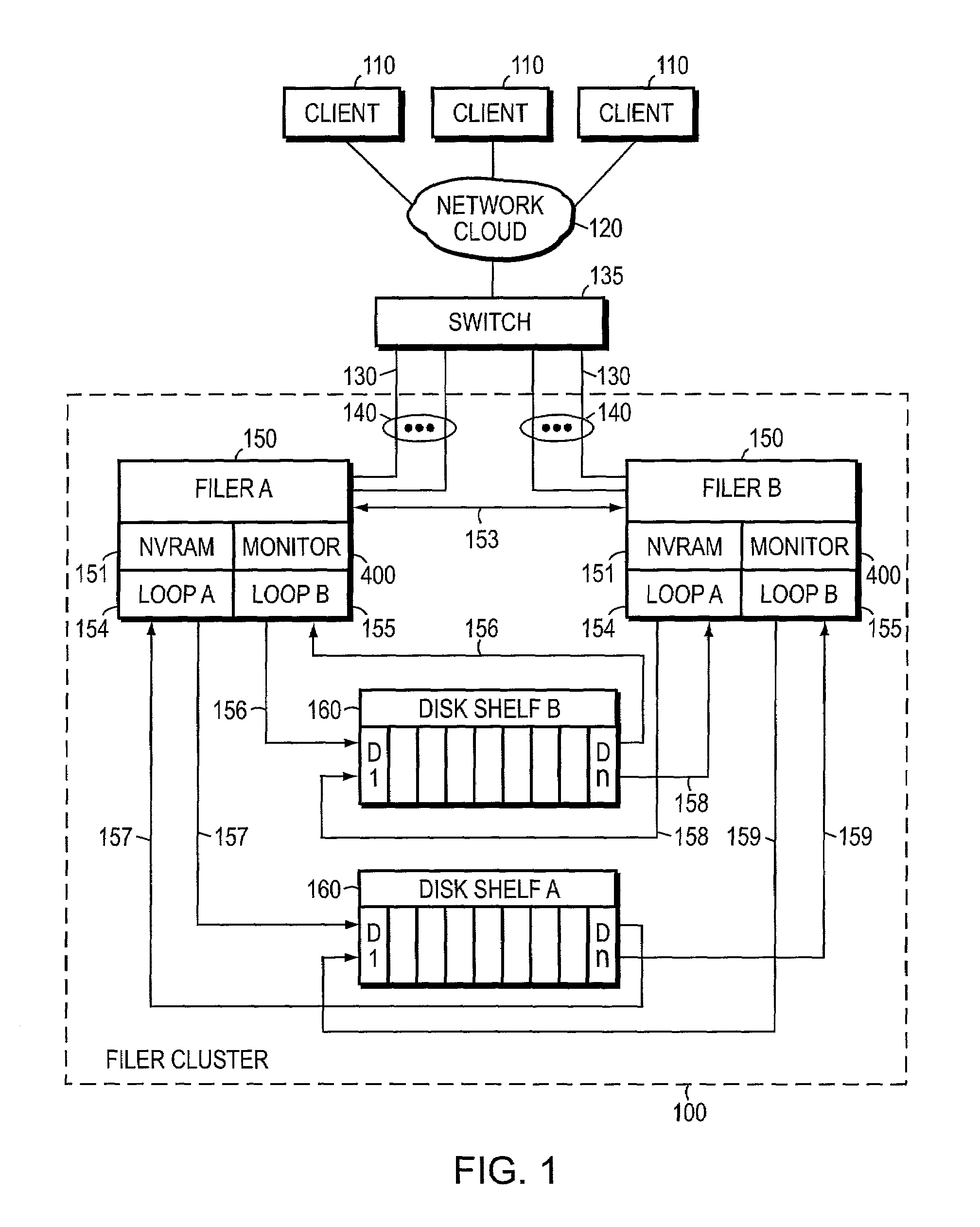
[0028]FIG. 1 is a block diagram of two storage systems or filers designated filer A 150 and filer B 150 connected as two nodes in a storage system or filer cluster 100 as shown. In accordance with the teaching of the invention, filer A and filer B provide takeover to protection to each other when one fails. It should be understood that while only two filers and two disk shelves are shown in the cluster configuration shown in FIG. 1, this has been done solely for the sake of brevity, and multiple filers and disk shelves may be connected in a cluster configuration and provide takeover for each other. Further, there may be more than one RAID group and multiple volumes within multiple RAID groups associated with each filer. In this specification the terms filer, file server and storage system are used synonymously. In FIG. 1 filers A & B are preferably file servers configured to provide file services relating to the organization of information on storage devices, such as hard disks D1-Dn in disk shelves A & B 160.
[0029]A client 110 may be a general-purpose computer, such as a PC, configured to execute applications, and operating systems that include file system protocols such as NFS and CIFS. Moreover, each client 110 may interact with a filer 150 in accordance with a client/server model of information delivery. That is, a client 110 may request the services of a filer 150 to retrieve files requested by the client. Clients 110 access filers 150 in cluster 100 via network cloud 120, switch 135 and communication links 130 that may be arranged in aggregates or bundles 140. In the following paragraphs the description is often singularly referenced to filer A or B, but it should be kept in mind that the description also applies to the other filer.
[0030]As part of cluster operation, filers A & B have primarily assigned to each of them a disk shelf 160 comprised of hard disk storage devices D1-Dn that operate in a manner well known in the art. The filers are controlled by the Data ONTAP™ storage operating system available from Network Appliance, Inc. This operating system implements a Write Anywhere File Layout (WAFL) on the disk shelves.
[0031]To understand the failover operation described further in this specification, it is important to understand that filers A & B access both disk shelves A and B. Filer A accesses its disk shelf A via loop A 157, and accesses disk shelf B via loop B 156. Similarly, filer B has primarily assigned to it a disk shelf B that it accesses via its loop A 158, and it accesses disk shelf A via its loop B 159. This joint access is necessary for a non-failed filer to access a failed partner's disk shelf to continue providing file services to the clients of the failed partner after a takeover.
[0032]To implement a takeover in the event of failure of a filer, filers A & B must communicate with each other in a peer-to-peer capacity across one or more communication links, such as cluster interconnect 153. The cluster interconnect can utilize any communication medium and protocol, including a Fibre Channel and a Server Net Fail-over link, both of which are commonly known in the industry. Fibre Channel is the general name is of an integrated set of standards used for apparatus to quickly transfer data between all types of hardware in the computer industry.
[0033]Each filer has a failover monitor that continuously checks and records the status of hardware and software associated with the filer, and the current status of file service requests being processed by the filer. This information is kept in non-volatile random access memory (NVRAM) 151 in each filer. The NVRAM in each filer is organized into two halves or segments. One half (i.e. the “local half”) of the NVRAM is used to store information about the hardware, operations and WAFL and RAID logs of the local filer, and the other half (i.e. the “partner half”) of the NVRAM is used to store similar information of its partner that is used when the filer takes over operations for the failed partner. More particularly, WAFL log and RAID log information of a filer are stored in the local half or segment of the filer's NVRAM and similar information of the partner filer is stored in the partner half or segment of the NVRAM. The information in the NVRAM of both filers is continuously updated. However, this mode of operation makes it hard to reconfigure the partner half of NVRAM because once NVRAM is initialized, different logs with different sizes are created and there is no mechanism to “grow” these areas of NVRAM.
[0034]A local filer that has taken over from a failed partner takes over the disks and replays the WAFL and RAID log entries of the failed partner stored in its NVRAM. As part of this takeover the local filer takes on two identities: its own identity and the identity of the failed partner. In addition, the local filer also activates network interfaces and network addresses that replicate the failed partner's network addresses. The identity, replicated network interfaces and network addresses are used until the failed partner is restored and control is returned to it. When the restored filer restarts after a system failure or power loss, it replays any NFS/CIFS requests in its NVRAM that have not been flushed and stored on hard disk.
[0035]After the local filer has taken over the operations of its failed partner, and the partner's mirrored log information has been flushed from the local filer's NVRAM to hard disk, the WAFL section of the partner half of the NVRAM is used by the local filer to increase the size of its WAFL log capacity and thereby improve operation of the local filer during takeover. This operation is described in greater detail further in this detailed description.
[0036]FIG. 2 is a block diagram of filer 200 comprising a processor 202, a memory 204, a storage adapter 206 and at least one network adapter 208 all interconnected by a system bus 210, which is preferably a conventional peripheral computer interconnect (PCI) bus. Storage adapter 206 is connected to disks 216 via a Fibre Channel link. The filer also includes a storage operating system 230 stored in memory 204 that implements a file system to logically organize information stored as a hierarchical structure of directories and files on the disks in an assigned disk shelf 212. The filer also includes an NVRAM 214 and cluster interconnect 153. Disks in the disk shelf are typically organized as a RAID 4 (Redundant Arrays of Inexpensive Disks) array to protect against data loss caused by disk failure in a manner well known in the art. RAID arrays also improve data availability because a filer can continue operation even with a single failed hard disk. In the illustrative embodiment described herein, the operating system 230 is preferably the Data ONTAP™ storage operating system 300 available from Network Appliance, Inc. that implements a Write Anywhere File Layout (WAFL) file system on the RAID 4 array.
[0037]Memory 204 is organized into storage locations that are addressable by processor 202 and network adapters 208 for storing software application programs 220 and the storage operating system 230. The processor executes the operating system and software applications stored in the memory. It will be apparent to those skilled in the art that other processing and memory means, including various computer readable media, may be used for storing programs and executing program instructions. Details of the operating system, WAFL and RAID components, networking components and failover components are described with reference to FIG. 3. Storage operating system 230 functionally organizes the filer by invoking storage and network operations in support of the services implemented by the filer.
[0038]Storage adapter 206 cooperates with storage operating system 230 executing on processor 202 to access client requested information stored on hard disks 216. Storage adapter 206 includes input/output (I/O) interface circuitry that couples to the disks 216 over an I/O interconnect arrangement, such as a conventional, high-performance, Fibre Channel serial link topology (not shown). Storage adapter 206 retrieves the stored information, which is then processed, if necessary, by processor 202 (or storage adapter 206 itself) prior to being forwarded over system bus 210 to a network adapter 208. The network adapter 208 formats the retrieved information into packets and returns them via a network (not shown) to a client 110 (not shown) that requested the information.
[0039]Each network adapter 208 in FIG. 2 may comprise a network interface card (NIC) having the necessary mechanical, electrical and signaling circuitry needed to connect a filer to a network node switch 135 via the physical communication links 130, both shown in FIG. 1.
[0040]FIG. 3 is a block diagram of the Data ONTAP™ storage operating system 300 available from Network Appliance, Inc. The storage operating system 300 implements the specialized file server operations of the Data ONTAP™ storage operating system on each filer. The operating system comprises a series of software layers, including a media access layer 310 of network drivers (e.g., an Ethernet NIC driver) that function with network adapters 208 in FIG. 2. Operating system 300 further includes network protocol layers, such as the IP layer 312 and its supporting transport mechanisms, the Transport Control Protocol (TCP) layer 314, and the User Datagram Protocol (UDP) layer 316. A file system protocol layer includes support for the Common Interface File System (CIFS) protocol 318, the Network File System (NFS) protocol 320 and the Hypertext Transfer Protocol (HTTP) protocol 322. In addition, the operating system includes a disk storage layer 324 that implements a disk storage protocol, such as the Redundant Array of Independent Disks (RAID 4) protocol, and a disk driver layer 326 that implements a disk access protocol.
[0041]The storage operating system 300 includes additional software layers, such as cluster interconnect layer 334 for controlling the operation of the cluster interconnect link 153 between filers A & B in FIG. 1 and a failover monitor 332 that determines the state of health of the cluster partner. An open firmware layer 328 disposed over the BIOS of each operating system allows changes to boot environment variables to thereby change the way a filer boots. This is advantageous during a reboot.
[0042]Bridging the network system and file system protocol layers in the operating system is a file system layer 330 that controls storage and retrieval of data on disks in each disk shelf. The file system layer 330 includes a consistency point (CP) process 325 that handles flushing of WAFL log information in the logs 0 & 1 and log 0 & 1 extensions to hard disk, and tracking the occurrence of consistency points when a log extension 0 or 1 are filled, as described briefly in the Summary of the Invention, and described in greater detail with reference to FIG. 5. Cleaner process 327 cooperates with CP process 325 to empty logs and log extensions following their flush to hard disk at a CP. Both cleaner process 327 and CP process 325 interact with a WAFL process 329 that controls the operation and use of the logs and log extensions in accordance with function “calls” disclosed herein.
[0043]In an alternate embodiment of the invention, some functions performed by the storage operating system may be implemented as logic circuitry embodied within a field programmable gate array (FPGA) or an application specific integrated circuit (ASIC). This type of hardware implementation increases the performance of the file service provided by a filer in response to a file system request issued by a client 110. Moreover, in another alternate embodiment of the invention, the processing elements of network and storage adapters may be configured to offload some or all of the packet processing and storage access operations, respectively, from the processor 202 to thereby increase the performance of the file service provided by the filer.
[0044]If the failover monitor 332 in the local filer determines that there is a failure in the partner filer that requires it to take over the partner filer, the local filer takes over the operations of its partner. An example of a method for a filer to take over the operations of another filer is described in U.S. patent application Ser. No. 09/933,883 entitled NEGOTIATED GRACEFUL TAKEOVER IN A NODE CLUSTER, which is incorporated by reference herein.
[0045]As previously described, after a local filer takes over filer operations for a failed partner, and uses the mirror image RAID and WAFL log information of the failed partner to establish the takeover, the stored mirror information is “flushed” from the local filer's NVRAM to hard disk. When takeover is completed the failed partner no longer writes to its partner portion of the local filer's NVRAM. That portion of NVRAM is empty and priorly was not utilized during the remainder of the takeover. In the illustrative embodiment described herein, only the WAFL portion of the partner's NVRAM space is used to provide additional NVRAM WAFL log space in accordance with the teaching of the present invention. The other portions of the failed partner NVRAM space remain unused during takeover. However, it will be apparent to those skilled in the art that the remaining unused memory in the partner's NVRAM may also be used to provide additional NVRAM log space.
[0046]FIG. 4 shows the organization of local filer NVRAM 400 resident in local filer A and the organization of partner filer NVRAM 405 resident in partner filer B. A segment or portion 410 (“local half”) of the local filer NVRAM is used to store its syslog, RAID log and WAFL log, while segment or portion 415 (“partner half”) is used to store a mirror image of the partner filer's syslog, RAID log and WAFL log information.
[0047]Similarly, segment or portion 420 of the partner filer NVRAM 405 is used to store its syslog, RAID log and WAFL log, while segment or portion 425 is used to store a mirror image of the local filer's syslog, RAID log and WAFL log information. The mirror image storage is represented by the arrows between the blocks representing the local filer NVRAM 400 and partner filer NVRAM 405. The local filer's WAFL log is stored in the “local WAFL log”425 of the partner filer and visa versa.
[0048]The size of the WAFL log in NVRAM is variable. It is typically sized sufficiently to log either certain time-based portions of transactions (for example, 100 milliseconds), or until a log 0 or log 1 is filled. The NVRAM is filled in parallel with a buffer cache in the filer but, as described above, is cleared and refilled after each CP is initiated, representing a confirmed write to hard disk of the log data.
[0049]The WAFL logs in each NVRAM 405 and 410 have three sections: the WAFL header, log 0 and log 1. The normal WAFL operation using logs 0 and 1 is described in detail in the Background of the Invention. The WAFL header contains a plurality of data structures configured to store information pertaining to the organization and structure of logs 0 and 1 in NVRAM. For example, the data structures are configured to store information indicating: (i) the number of entries in each log, (ii) the starting and ending addresses of each log, and (iii) which log is currently in use. Note that the entries of logs 0 and 1 are generally not of a fixed length. However, each entry is of a particular type and each type of entry has a fixed length.
[0050]During takeover, the failover monitor 332 in FIG. 3 interacts with the disk driver layer 326 to assert disk reservations (i.e. change ownership of disks from the failed partner to the local filer), while the cluster interconnect 334 interacts with the failover monitor 332 to send a “please die” command to the failed partner. In addition, the WAFL process 329 interacts with CP 325 and cleaner 327 to flush the WAFL section of the partner half of the local filer's NVRAM to hard disk and reset the NVRAM log entry count to zero. The free WAFL log portion 415 of local filer NVRAM 400 is then used to provide additional NVRAM WAFL log space in accordance with the teaching of the present invention.
[0051]FIG. 5 shows the organization of local filer NVRAM 400 following takeover of service from its failed partner. To provide additional NVRAM space in local filer NVRAM 400 to be used to expand the WAFL log during a takeover, the now empty and unused partner WAFL log 0 and log 1 in partner NVRAM space 415 are re-used as WAFL log extensions 502&503. That is, after flushing partner information to disk, the partner WAFL log sections 502&503 in partner half 415 of the local NVRAM 400 are used as extensions to the local WAFL log sections 505&506 in local half 410 of NVRAM 400. In particular, log 0 of partner half 415 becomes log 0 extension (502) to log 0 (505) of local half 410, and log 1 of partner half 415 becomes log 1 extension (503) to log 1 (506) of local half 410. The memory size and organization of log 0 and 1 extensions 502 and 503 are the same as the memory size and organization of local WAFL log 0 and 1 in local NVRAM portion 410. The directory, syslog and RAID log memory space in the partner NVRAM space 415 remain unused after they are flushed during takeover, as represented by the blank blocks in FIG. 5.
[0052]Additional information is needed in the local WAFL section header 430, indicating whether or not log 0 & 1 extensions are being used and where the extensions begin and end. According to the teaching of the invention, information is added to a data structure (e.g., WAFL_NVLOG1 Log X) in the header. The description regarding FIG. 6 provides more detail.
[0053]During takeover the operation of storing service requests in local WAFL log 0 (505) and local WAFL log 1 (506) and their extensions 502 and 503 in local filer NVRAM 400 is essentially the same as in the prior art with one difference. Once local log 0 (505) is filled, a consistency point (CP) is not initiated; rather, WAFL stores additional service requests in the log 0 extension (502). When both log 0 and log 0 extension are filled a CP is initiated. The entries in log 0 and log 0 extension are flushed to hard disk, and the log 0 and log 0 extension NVRAM locations are erased as previously described with reference to CP 325 and cleaner 327. At the same time subsequent service request entries are stored in local log 1 (506) and, when it is filled, further service requests are stored in the log 1 extension (503). When both log 1 and log 1 extension are filled another CP is initiated. The entries in the log 1 and log 1 extension are flushed to hard disk, and the log 1 and log 1 extension NVRAM locations are erased. At the same time subsequent service request entries are again stored in log 0 (505) and then in log 0 extension (502) as previously described. Both local filer and partner filer requests are interleaved as entries within the WAFL logs. Therefore, the invention essentially doubles the size of the WAFL logs during takeover, and half the number of CPs are invoked which increases performance while simplifying operation of the local filer.
[0054]In non-takeover operation, when either log 0 or log 1 is full a CP is initiated and there is a transfer to the other of the two logs as previously described. This is followed by flushing the full log's contents to hard disk, freeing those log contents from the NVRAM, and resetting the log entry count to zero. In a takeover operation, however, the WAFL file system maintains a log count to ascertain when logs 0 and 1 and their extensions are filled. Specifically, since there is no CP initiated when log 0 or 1 is filled during takeover, a WAFL log allocation routine (e.g. ALLOC_NVLOG_ENTRY) checks to the log full condition so as to be made aware of log extension use. This prevents a CP from being initiated until both a log and its log extension are filled.
[0055]In addition, when service requests are stored and replayed, the WAFL layer needs to be aware of the creation of the extensions used to store and replay entries in the extensions. To do this the number of file service entries in the original log and in the log extension must both be known. In the illustrative embodiment the number of entries are determined by counters that are maintained by WAFL, in e.g., the local WAFL header 430. For example, a first counter maintains a “primary log count” where the number of log entries in the original log is kept during takeover, whereas a second counter and the existing “entry_cnt” field (normally used to store the number of log entries in the original log) is used to track the total number of entries in the log and its log extension. The difference between these two numbers is the number of entries in the log extension. This information may be used in connection with other information contained in data structures of the WAFL header 430 to thereby enable control of the various sections of the NVRAM in accordance with the teaching of the invention.
[0056]FIG. 6 is a block diagram illustrating a WAFL data structure 600 used to control the WAFL log 0 (606) and log extension 0 (608) sections of the NVRAM. In the illustrative embodiment, the log 0 data structure is organized to store information directed to log 0 (606) and its extension Ext log 0 (608). Specifically, field 601 of the data structure contains the address (e.g. a start pointer) of the starting location in NVRAM for log 0, and field 602 contains an end pointer referencing the ending location in NVRAM of log 0.
[0057]According to the teaching of the invention, the log 0 data structure (600) is modified to include a field 603 containing an extension start pointer referencing the starting location of Ext log 0 (608) in NVRAM, and field 604 contains an EXT end pointer referencing the ending location of Ext log 0 (608) in NVRAM. In addition, a field 605 is provided to contain an Ext Valid flag indicating whether or not Ext log 0 is currently in use. The flag is set to 0 when Ext log 0 is not in use, and is set to 1 when Ext log 0 is in use.
[0058]It should be noted that a data structure similar to log 0 (600) is provided to enable access and control to log 1 (607) and its extension Ext log 1 (609).
[0059]Operation of the invention will now be described with reference to FIGS. 1-6. Assume an NFS incoming request packet is processed at the media access layer 310 and TCP/IP layer 314 in FIG. 3, prior to being forwarded to NFS layer 320, which determines the packet type. The file system layer 330 processes the request by determining the is amount of space needed to store the request in NVRAM and then calls the function ALLOC_NVLOG_ENTRY requesting an entry in log 0/1 to “log” a certain amount of data. ALLOC_NVLOG_ENTRY “knows” how much space is available in the WAFL section of NVRAM and whether the request can be accommodated in the currently used log 0 or 1. If so, an entry is created in that current log and the request data is loaded into the entry. If there is not enough space in the log 0 or 1, the entry is created in the appropriate one of log extensions 0 or 1 and the data is stored in that entry. This same operation applies to tracking space for storing entries in the log extensions.
[0060]If there is not enough space in a log extension, ALLOC_NVLOG_ENTRY returns an indication of “no space available,” which then triggers a CP as logs are switched from 0 to 1, or 1 to 0. Once a CP is initiated, WAFL is switched to the other log and its extension to store further requests.
[0061]For example, when log 0 (505) is full, requests are directed to log 0 extension (502) using the extension log 0 start address 603 and without initiating a CP. New requests are then logged to log extension 0 (502) in the NVRAM. When log extension 0 (502) is full, a CP is initiated. Once a CP is initiated, WAFL is switched to log 1 (506) for use in storing requests.
[0062]The above described operation of using a failed filer's WAFL log in its partner's NVRAM for a log extension has an advantage of simplifying operations. Using the example of a local filer taking over for a failed partner filer, as reflected in the local filer NVRAM shown in FIG. 5, the offset from local header 501 to local log 0 (505) is the same as the offset from header 509 to file log 0 extension (502), and the offset from local header 501 to local log 1 (506) is the same as the offset from header 509 to file log 1 extension (503).
[0063]At some point in time whatever problem caused a partner filer to fail will be cured and the local filer will transfer file server operations back to the partner. This will occur to when either the partner filer will be repaired or rebooted, or failed equipment with which the partner functions will be repaired. The determination to giveback file server operations to the restored partner may happen in either of two ways: (1) the local filer receives a giveback_operation command from a system operator, or (2) the local filer receives a message from the partner that it has recovered from the failure and is in its rebooting state. In the latter case the local filer initiates the giveback_operation command.
[0064]For a giveback operation during a “takeover to normal” mode transition of the cluster, the invention contemplates flushing of the data in both the logs and their log extensions to hard disk. Giveback processing assumes a reverse order of operation from that followed by takeover processing. Here replay of the WAFL logs involves forcing a CP, which flushes all data of a log to disk.
[0065]Moreover, the invention further contemplates a “panic giveback” situation during takeover. A panic situation arises when there is an exception that the storage operating suystem cannot handle gracefully and continue operating. A panic situation causes the storage operating system to “halt”, save the contents of memory in a core file and reboot. There are three typical scenarios one can envisage when considering a panic situation in a cluster.
1) The filer was running in normal (local, non-takeover) mode when the panic situation was encountered. In this case, the system reboots into non-takeover mode.
2) The filer was running in takeover mode for longer than PANIC_GIVEBACK_TIMEOUT seconds when the panic situation was encountered.
In this case, the system reboots into takeover mode.
[0066]3) The filer was attempting to transition from normal to takeover mode or the filer had completed the transition to takeover mode less than PANIC_GIVEBACK TIMEOUT seconds ago. In this case, if the filer were to reboot into takeover mode, it could encounter the panic situation again. This would lead to another reboot attempt, which could encounter the panic situation again. This could continue indefinitely. In order to obviate this, the filer reboots into normal mode rather than takeover mode.
[0067]The last case is interesting because the filer transitions from takeover mode to normal mode during reboot. The NVRAM of the filer initially contains requests directed to the failed partner and the log extensions are valid. All requests directed to the failed partner must be flushed to hard disk and the log extensions must be made unavailable before the transition is completed. This is accomplished by having a variable in the cluster failover monitor code configured to delay the indication that the log extensions are unavailable for use until after the contents of the NVRAM are flushed. This prevents is loss of data in the extensions.
[0068]More specifically, during giveback the state transitions go from BOTH_EXTS_VALID to ONE_EXT_VALID to BOTH_EXTS_INVALID during two CPs that are forced during the giveback operation.
[0069]In an alternative embodiment of the invention the same NVRAM method and hardware taught herein to expand NVRAM space used for WAFL logs during takeover can be used to expand NVRAM space used for RAID logs during takeover. With reference to FIG. 5, during takeover the local RAID log 507 can be filled and additional information stored in a RAID log extension 508 in NVRAM space 415 until it is filled before the RAID log information is flushed to hard disk.
[0070]In yet another alternative embodiment of the invention the logs and log extensions need not be filled in the same order as described for the preferred embodiment of the invention. For example, local logs 0 (505) and 1 (506) may be filled before a CP, then local log 0 extension (502) and local log 1 extension (503) filled before the next CP.
[0071]In another alternative embodiment of the invention the size of the local WAFL log extensions 502 and 503 can be further increased by including therein the unused partner header, partner RAID log and partner WAFL header memory locations of partner NVRAM 415.
[0072]Although the preferred embodiment of the apparatus and method of the present invention has been illustrated in the accompanying drawings and described in the foregoing Detailed Description, it is understood that the invention is not limited to the embodiments disclosed, but is capable of numerous rearrangements, modifications and substitutions without departing from the spirit of the invention as set forth and defined by the following claims. For example, the preferred embodiment of the invention described herein is used in a cluster of file servers, but the teaching of the invention may be applied to clustered servers of different types.
Login to view more PUM


Description & Claims & Application Information
We can also present the details of the Description, Claims and Application information to help users get a comprehensive understanding of the technical details of the patent, such as background art, summary of invention, brief description of drawings, description of embodiments, and other original content. On the other hand, users can also determine the specific scope of protection of the technology through the list of claims; as well as understand the changes in the life cycle of the technology with the presentation of the patent timeline. Login to view more.
Login to view more Similar technology patents
Apparatus and method for high speed IPSec processing
ActiveUS20060265585A1Enhance performanceHigh performanceUnauthorized memory use protectionHardware monitoringSafety EquipmentEncryption
Owner:A10 NETWORKS
Hybrid speech coding and system
ActiveUS7139700B1Enhance performanceAvoid phase discontinuitySpeech analysisWaveform codingSpeech code
Owner:TEXAS INSTR INC
Rotary gyroscope
ActiveUS7043987B2Enhance performanceResistant to deformationAcceleration measurement using interia forcesSpeed measurement using gyroscopic effectsDriven elementIntermediate structure
Owner:SAMSUNG ELECTRONICS CO LTD
Cellulose filled thermoplastic composites
Owner:NAT RES COUNCIL OF CANADA
Self-condensing pH sensor and catheter apparatus
ActiveUS20060270940A1Enhance performanceSimplification of placeMaterial analysis by electric/magnetic meansRespiratory organ evaluationData loggerRadio frequency
Owner:SIERRA MEDICAL TECH
Classification and recommendation of technical efficacy words
- Increase storage capacity
- Enhance performance
Display apparatus
InactiveUS20020024493A1Increase storage capacityIncrease emission luminanceStatic indicating devicesElectroluminescent light sourcesVIT signalsN channel
Owner:INTELLECTUAL KEYSTONE TECH
Using LUN type for storage allocation
ActiveUS8086603B2Increase storage capacitySolve insufficient storage spaceDigital data processing detailsSpecial data processing applicationsData typeData library
Owner:NETWORK APPLIANCE INC
Nanostructured anode for high capacity rechargeable batteries
InactiveUS20100062338A1Increase storage capacityMitigate active material degradationSecondary cellsNon-aqueous electrolyte accumulator electrodesVolume expansionSilicon nanoparticle
Owner:LOCKHEED MARTIN CORP
Vanity cabinet with drawers
Owner:LOWE MARK JEFFREY
Device and method for recording and saving voice call on mobile phone
InactiveCN101155357AIncrease storage capacityEasy to useAutomatic call-answering/message-recording/conversation-recordingRecord information storageWord searchSpeech sound
Owner:YINGHUADA (SHANGHAI) ELECTRONIC CO LTD
Pulse oximeter sensor with piece-wise function
InactiveUS20060030763A1Enhance performanceColor/spectral properties measurementsSensorsCalibration coefficientPulse oximetry
Owner:TYCO HEALTHCARE GRP LP
Method and apparatus for body position monitor and fall detect ion using radar
ActiveUS7567200B1Enhance performanceSave on network resource and process powerUltrasonic/sonic/infrasonic diagnosticsDirection finders using radio wavesEnvironmental geologyFall detector
Owner:THE OSTERWEIL FAMILY TRUST
Chassis construction for an article of footwear
InactiveUS6954998B1Enhance performanceEffective power transferSolesUpperEngineeringMechanical engineering
Owner:ADIDAS
Data processing apparatus of basic input/output system
ActiveUS20100281225A1Enhance performanceLower probabilityMemory adressing/allocation/relocationDigital computer detailsInput/outputData processing
Owner:INVENTEC CORP
Method and apparatus for image-based eye tracking for retinal diagnostic or surgery device
ActiveUS20050270486A1Improve accuracyEnhance performanceImage enhancementLaser surgeryImage basedMotion estimation
Owner:SENSOMOTORIC INSTR FUR INNOVATIVE SENSORIK MBH D B A SENSOMOTORIC INSTR +1