Interlocking tooth bond for assembly of fiber composite laminates

a technology of interlocking tooth and fiber composite laminate, which is applied in the direction of transportation and packaging, other domestic articles, and efficient propulsion technologies. it can solve the problems of the resin itself not being able to arrest the growth, the most common type of failure of fiber composite laminate, and the relatively low damage tolerance of the fiber composite laminate. it achieves the effects of reducing interlaminar stresses, improving damage tolerance, and weight and cost efficiency

Active Publication Date: 2010-06-08
BELL HELICOPTER TEXTRON INC
View PDF16 Cites 17 Cited by
  • Summary
  • Abstract
  • Description
  • Claims
  • Application Information

AI Technical Summary

Benefits of technology

[0013]Therefore, it is an object of the present invention to provide an improved method of joining fiber composite laminates that is weight and cost efficient while offering improved damage tolerance relative to existing bonded joint configurations.
[0014]This object is achieved by providing a method of joining fiber composite laminates in which the bonding is done through the thickness of the fiber composite laminates to reduce the interlaminar stresses typical of other configurations. There are two ways to form the bond: (1) non-interlocking; and (2) interlocking.
[0015]The present invention provides significant advantages, including: (1) fiber composite laminates can be joined end-to-end without additional build-up of the laminates; (2) structural cover plies are not required, but may be used; (3) the probability of interlaminar failures is greatly reduced; (4) visual inspection of the joint is possible; (5) cover plies can be used for additional strength or damage indication; (6) extra location tolerance is provided in large structural assemblies; (7) joint geometry overcomes interlaminar weakness; (8) joints exhibit failsafe capability, in that a limit load or portion of the ultimate load can be carried after adhesive failure; (9) joints are energy absorbing, in that there is stroking or movement of the joint under load prior to failure; (10) joints have higher specific strengths than bonded or bolted joints; (11) joint is low profile, which reduces weight, eliminates eccentricity, and increases aerodynamic smoothness; (12) performance of joints after being damaged is more predictable; (13) tooth profiles can be selectively modified to achieve different performance characteristics; (14) energy absorption can be increased; and (15) inherently brittle material can be made to produce a ductile response.

Problems solved by technology

A significant problem with fiber composite laminates is their relatively low damage tolerance.
However, the resin itself is not capable of arresting the growth of cracks and interlaminar failures known as delamination.
Delamination, the most common type of failure in fiber composite laminates, most often begins at the edges of the plies at the ends of the fiber composite laminate and at joints.
Over the years, one of the greatest challenges faced by designers who work with fiber composite laminates is how to join two fiber composite laminates together.
However, because fiber composite laminates are so difficult to join together there is always additional bulk, weight, and cost associated with making joints that are sufficiently strong and safe.
This adds bulk and weight to the structure.
Single lap joints are the least efficient and have the lowest damage tolerance.
Because the two fiber composite laminates are overlapped, tension loads cause the two laminates to peel away from each other, resulting in interlaminate delamination at the ends of the laminates.
Although the ends of the fiber composite laminates can be chamfered or tapered, the joint is still susceptible to peel and delamination.
This typically results in a tension failure of the adhesive in the butt joint or an interlaminar shear failure initiating at one of the ends of the cover plies where the cover plies are adhered to the outermost layers of the fiber composite laminate.
In scarfed joints, although it is possible to eliminate the cover plies, there are other problems.
As such, scarf joints are very difficult and expensive to fabricate.
Bolted joints offer improved damage tolerance relative to the bonded joint options discussed above, but there are many other problems with bolted joints.
It is very difficult and expensive to drill precise holes with low tolerances in fiber composite laminates because the laminates are easily damaged during the drilling process.
Repeated loads on bolts cause bearing wear and brooming of the bolt hole.
Because the two laminates are overlapped, eccentricity is introduced into the load path, which causes bending and tension on the bolts and results in premature bolt failure.
Curvature further complicates all of these joints.

Method used


Image

  • Interlocking tooth bond for assembly of fiber composite laminates
  • Interlocking tooth bond for assembly of fiber composite laminates
  • Interlocking tooth bond for assembly of fiber composite laminates

Examples


Embodiment Construction

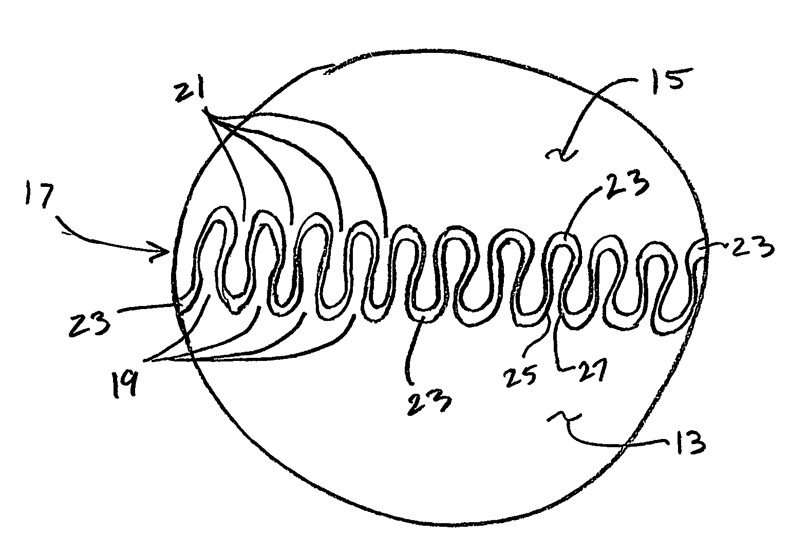
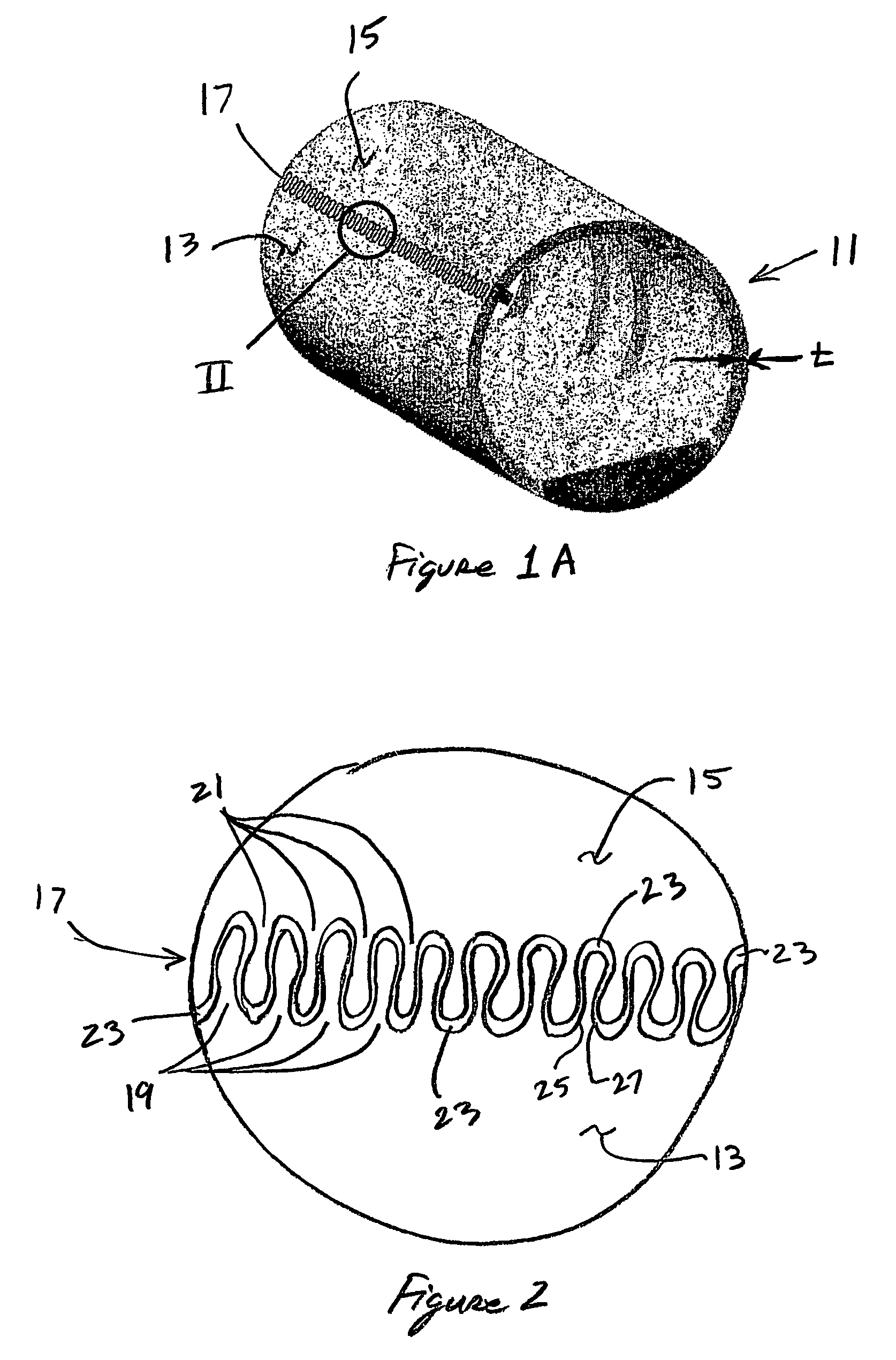
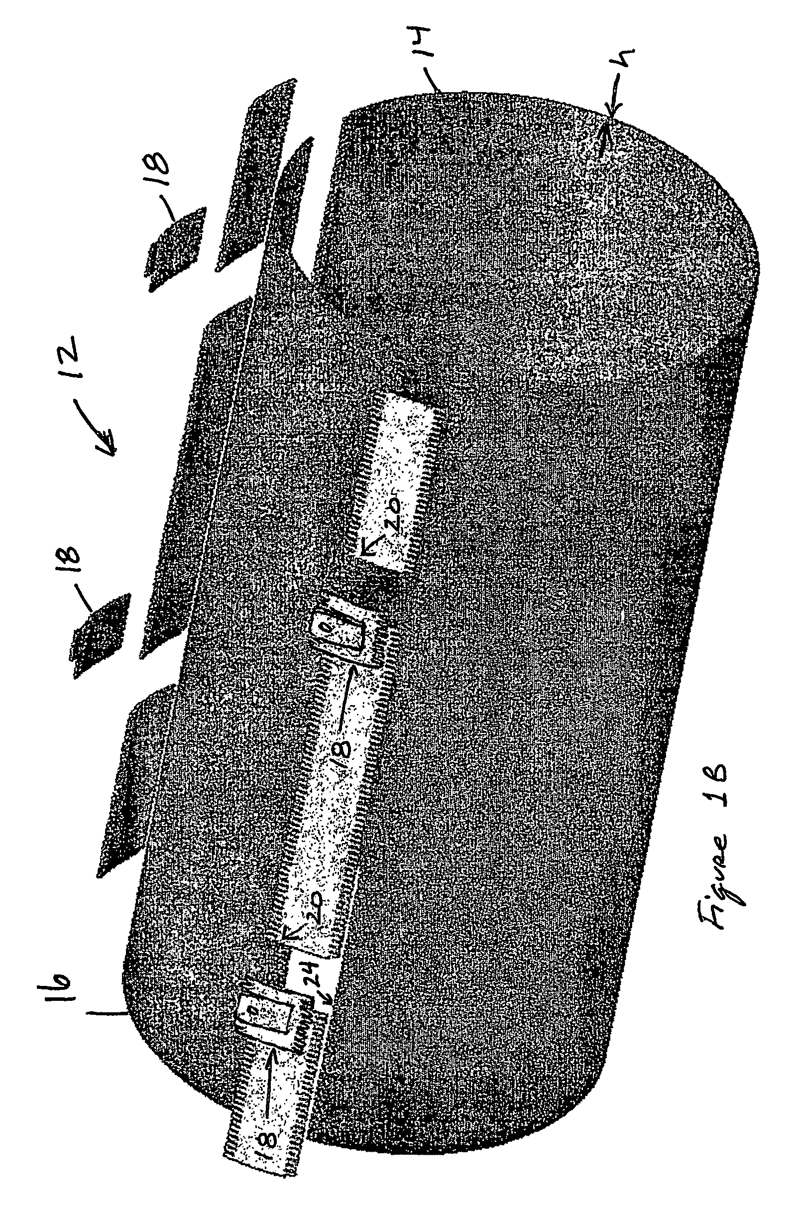
[0027]The present invention is an improved method of joining two fiber composite laminates together in an end-to-end fashion. The method produces a low profile adhesive bond for structurally splicing two fiber composite panels together. There are two main embodiments of the invention: (1) mechanically interlocking teeth; and (2) non-interlocking teeth. It will be appreciated that many combinations of interlocking teeth, non-interlocking teeth, and offset interlocking and a non-interlocking teeth may also be employed, depending upon the application in which the laminates are used. The tooth-type bond of the present invention virtually eliminates peel in the adhesive joint, thereby reducing the likelihood of an interlaminar failure. Laminates joined by the method of the present invention have substantially improved damage tolerance relative to conventional lap splice bonds. The bond geometry inhibits disbond cracks from propagating down the length of the joint and causing a catastroph...


PUM

PropertyMeasurementUnit
stress concentrationsaaaaaaaaaa
stress concentrationaaaaaaaaaa
thicknessaaaaaaaaaa

Abstract

An improved method of joining fiber composite laminates is disclosed. Two fiber composite laminates may be joined together end-to-end. The bonding is done through the thickness of the fiber composite laminates. There are two ways to form the bond: (1) non-interlocking; and (2) interlocking.

Description

TECHNICAL FIELD[0001]The present invention relates to the joining of fiber composite laminates.DESCRIPTION OF THE PRIOR ART[0002]Fiber composite laminates have been in use for many years. They are a high-strength, low-weight alternative to metallic parts. Fiber composite laminates are particularly well suited for use in the aircraft industry where reducing weight and increasing strength are of utmost importance.[0003]Fiber composite laminates are formed by building up multiple layers, lamina, or plies, of composite fibers one upon another. Each layer of fibers is oriented in a specific direction to provide particular properties to the laminate. In a typical laminate, some fibers extend parallel to the longitudinal axis, others extend transverse to the longitudinal axis, and others extend “off-axis” at various angles to the longitudinal axis. By laying up and orienting the fiber layers in certain configurations, the stiffness and other properties of the laminate can be predetermined....

Claims


Application Information

Patent Timeline
Patent Type & Authority Patents(United States)
IPC IPC(8): B32B37/12B32B37/18B32B38/04B32B3/06B29C59/00B29C59/02B29C65/00B29C65/50B32BB32B7/08B32B7/12B65H21/00
CPCB29C53/40B29C65/56B29C66/022B29C66/1142B29C66/20B29C66/2272B29C66/2274B29C66/43B29C66/4322B29C66/721B32B3/02B32B7/08B32B7/12B32B17/02B64C1/068B64C1/12B29C65/5042B29C65/4835B29C65/483B29C65/00Y10T428/198B29C65/54B29C66/0224B29C66/02241B29C66/223B29C66/227B29C66/2276B29C2793/0081B29K2105/06B29L2031/3082B29L2031/7126B64C2001/0072Y02T50/433Y10T156/1066Y10T428/193Y10T428/19Y10T428/17Y10T428/195Y10T428/197Y10T428/192B29C65/8253B29C65/542B29C66/72141B29C66/221Y02T50/40B32B2262/101B32B2605/18B32B5/26
Inventor HETHCOCK, JAMES DONNJONES, RODNEY H.
Owner BELL HELICOPTER TEXTRON INC
Why Eureka
Try Eureka