System and process for calibrating pyrometers in thermal processing chambers

a technology of thermal processing chamber and pyrometer, which is applied in the direction of optical radiation measurement, instruments, semiconductor/solid-state device testing/measurement, etc., can solve the problems of inability to accurately measure and requires a substantial amount of time to calibrate instruments, so as to reduce the differences in thermal characteristics and reduce the effect of thermal mass differences

a technology of thermal processing chamber and pyrometer, which is applied in the direction of optical radiation measurement, instruments, semiconductor/solid-state device testing/measurement, etc., can solve the problems of inability to accurately measure and requires a substantial amount of time to calibrate instruments, so as to reduce the differences in thermal characteristics and reduce the effect of thermal mass differences

US7734439B2Inactive Publication Date: 2010-06-08MATTSON TECHNOLOGY +1

Image

  • System and process for calibrating pyrometers in thermal processing chambers
  • System and process for calibrating pyrometers in thermal processing chambers
  • System and process for calibrating pyrometers in thermal processing chambers

Examples


Embodiment Construction

[0025]It is to be understood by one of ordinary skill in the art that the present discussion is a description of exemplary embodiments only, and is not intended as limiting the broader aspects of the present invention, which broader aspects are embodied in the exemplary construction.

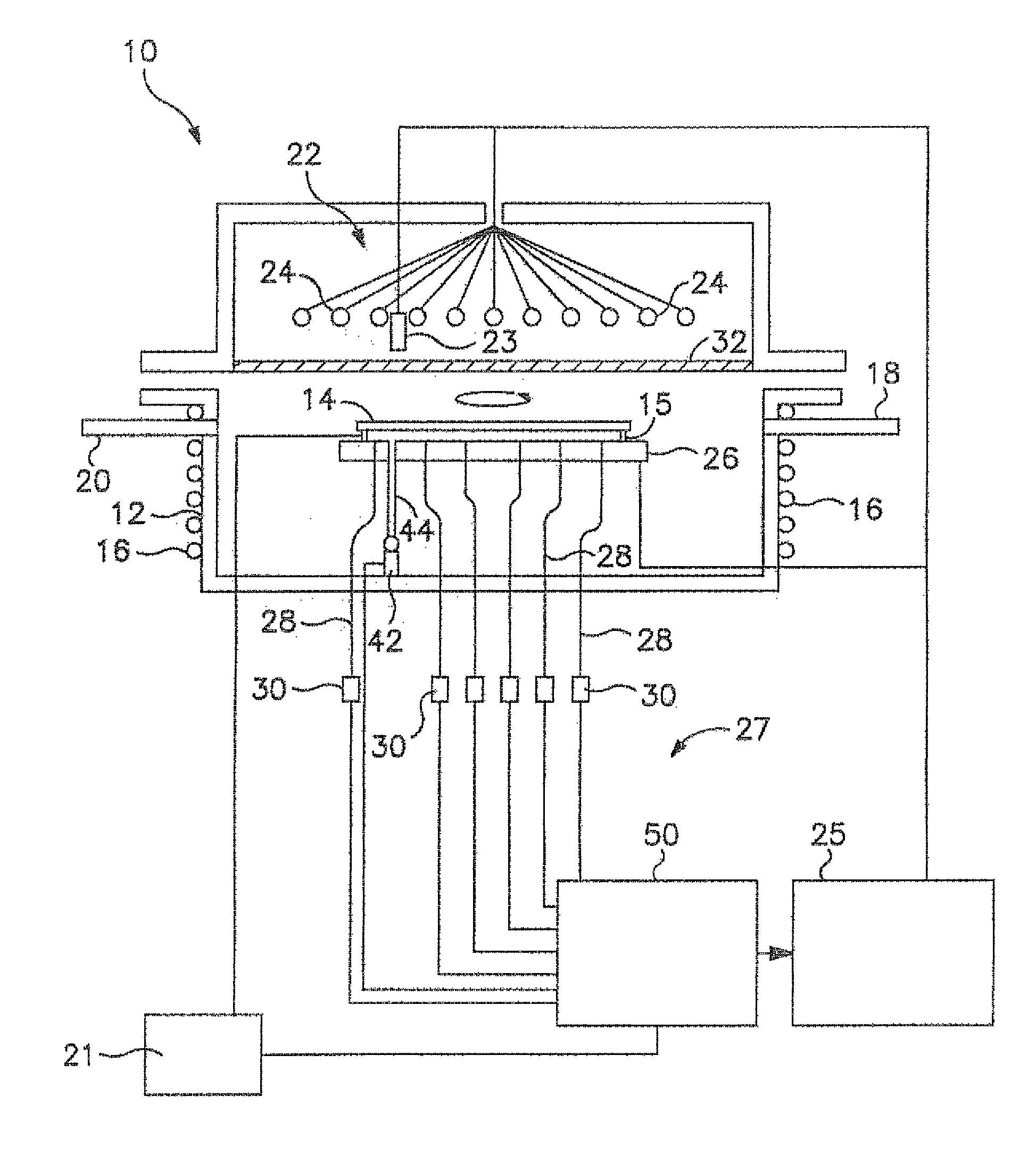
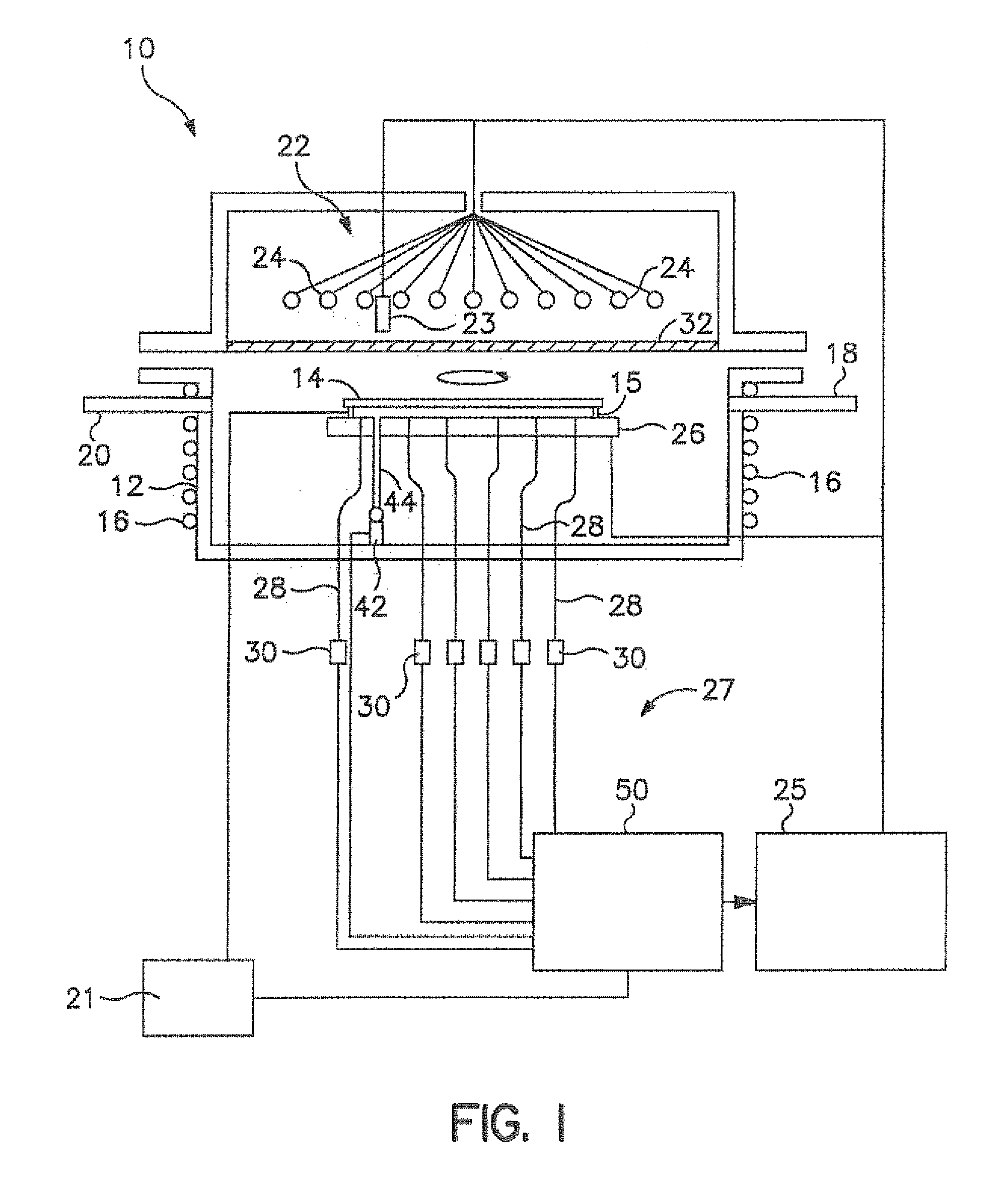
[0026]The present invention is directed to a method and to a system for more accurately determining and controlling the temperature of an object, particularly a semiconductor wafer in a thermal processing chamber during heat treatment. More particularly, the present invention is directed to a method and system for calibrating temperature measuring devices contained within thermal processing chambers so that the thermal processing chamber will operate more repeatably and accurately. For instance, it is important that temperature sensing devices contained within thermal processing chambers accurately measure the temperature of semiconductor wafers as they are being heated. In this regard, the temperature s...


PUM


Abstract

A method and system for calibrating temperature measurement devices, such as pyrometers, in thermal processing chambers are disclosed. According to the present invention, the system includes a calibrating light source that emits light energy onto a substrate contained in the thermal processing chamber. A light detector then detects the amount of light that is being transmitted through the substrate. The amount of detected light energy is then used to calibrate a temperature measurement device that is used in the system.

Description

BACKGROUND OF THE INVENTION[0001]A thermal processing chamber as used herein refers to a device that rapidly heats objects, such as semiconductor wafers. Such devices typically include a substrate holder for holding one or more semiconductor wafers and an energy source for heating the wafers, such as heating lamps and / or an electrical resistance heater. During heat treatment, the semiconductor wafers are heated under controlled conditions according to a preset temperature regime.[0002]Many semiconductor heating processes require a wafer to be heated to high temperatures so that various chemical and physical transformations can take place as the wafer is fabricated into a device. During rapid thermal processing, for instance, semiconductor wafers are typically heated by an array of lights to temperatures from about 300° C. to about 1,200° C., for times that are typically less than a few minutes. During these processes, one main goal is to heat the wafers as uniformly as possible.[000...

Claims


Application Information

Patent Timeline
08 Jun 2010
Publication
US7734439B2
IPC
G06F19/00; G01J5/58; G01J5/00; G01J5/06; G01J5/08; G01J5/52; H01L21/00; H01L21/26; H01L21/324; H01L21/66
CPC
G01J5/0003; H01L21/67248; G01J5/06; G01J5/08; G01J5/0803; G01J5/0821; G01J5/0831; G01J5/0846
Inventors
TIMANS, PAUL JANIS