High pressure gas tank cooling by ejector pump circulation

a gas tank and circulation technology, applied in liquid handling, packaging goods, container discharging methods, etc., can solve the problem of reducing the efficiency of internal heat exchangers to less than 100%, and achieve the effect of reducing energy loss, reducing heating of tanks, and increasing refueling efficiency in hydrogen refilling systems

Active Publication Date: 2010-06-15
HONDA MOTOR CO LTD
View PDF4 Cites 30 Cited by
  • Summary
  • Abstract
  • Description
  • Claims
  • Application Information

AI Technical Summary

Benefits of technology

[0009]It is an object of the present invention to minimize energy loss and increase refueling efficiency in hydrogen refilling systems when factored into the overall energy efficiency of an infrastructure of high pressure gas powered vehicles and fuel depots for the consumer dispensation of high pressure fuel. Typically, each time a vehicle is refueled with hydrogen, mechanical compression transforms into thermal energy and results in the heating of refueled gas in the tank, hence, it is an object of the invention to minimize tank heating and to increase the efficiency and refueling capacity of an on board fuel storage tank in a hydrogen powered motor vehicle. It is an object of the invention to minimize high pressure gas tank heating and to increase the efficiency and refueling capacity of an on board fuel storage tank in high pressure gas powered motor vehicles. It is an object of the invention to provide a system that can remove the compression heat resulting from refueling an on board tank during high pressure refueling. An avoidance of secondary gas cooling pretreatment and / or pressure overfill, a speedier refueling time, increased refueling efficiency, and an extension of overall vehicle range will result. Improved tank capacity per unit volume is achieved during refilling, particularly where nominal refill pressure is in the range of about 10,000 psi or greater for hydrogen and about 3,600 psi for CNG.SUMMARY OF THE INVENTION
[0010]The invention provides a system that can remove the heat of compression resulting from the high pressure refueling of an on board vehicle tank. Refueling time will decrease and refueling efficiency and overall vehicle range will increase as a result of the improved tank capacity per unit volume achieved by the tank gas cooling system described herein. In accordance with the present invention, effective reduction of fuel tank heating during the refueling process is provided by introducing the refueling gas into an ejector pump that sucks out the hot gas from within the tank and in a circuit introduces the hot gas into a heat exchanger where the gas is then cooled down. The cooled gas and the refueling gas are mixed in the ejector and then both gas streams are directed into the vehicle storage tank.
[0011]The system described herein provides onboard cooling; as a result, there is no need to change the refueling station equipment. The cost and weight of on board gas cooling equipment, important factors in the adoption of high pressure fueled vehicles, are reduced; there is no internal heat exchanger in the confines of the tank. Cooling capacity is improved; continuous cooling is provided. Heat exchange efficiency approaches 100%. When there is an internal heat exchanger, the gas temperature in the heat exchanger is not perfectly equal to tank gas temperature, thus reducing internal heat exchanger efficiency to less than 100%. In the gas ejector system described herein, the gas flow cooling circuit is interconnected with an external heat radiator, thereby collecting interior tank heat and radiating the absorbed heat into the ambient atmosphere or other system appropriate for the use, radiation, absorption, or disposal of the collected heat of high pressure refueling.
[0012]In brief, the invention provides a system for reducing the energy and for reducing the time required to refill on board tanks on a vehicle from a high pressure fuel depot refilling line operatively interconnected to the tank wherein the refilling gas itself is circulated within the on board tank to absorb the compression heat of refueling, and the heat thereby absorbed, is radiated from the cooling circuit to an external environment before the fuel reaches the tank such that a close to optimum refill of the tank is achieved.
[0013]It is an object of the invention to provide a gas jet ejector wherein a Venturi pump utilizes the energy in the high pressure gas to create a lower pressure that can entrain another gas stream. A gas jet ejector has no moving parts and requires no maintenance thereby providing a distinct advantage over mechanical pumps. Reliability is achieved in that once the motive pressure is set, the ejector performance is maintained over a range of operating conditions. Shutdown and restart are possible without complication. The pump connections, nozzle inlet, suction inlet and throat outlet, provide the jet (Venturi) pump that is conveniently adaptable to a high pressure environment.

Problems solved by technology

When there is an internal heat exchanger, the gas temperature in the heat exchanger is not perfectly equal to tank gas temperature, thus reducing internal heat exchanger efficiency to less than 100%.

Method used


Image

  • High pressure gas tank cooling by ejector pump circulation
  • High pressure gas tank cooling by ejector pump circulation
  • High pressure gas tank cooling by ejector pump circulation

Examples


Embodiment Construction

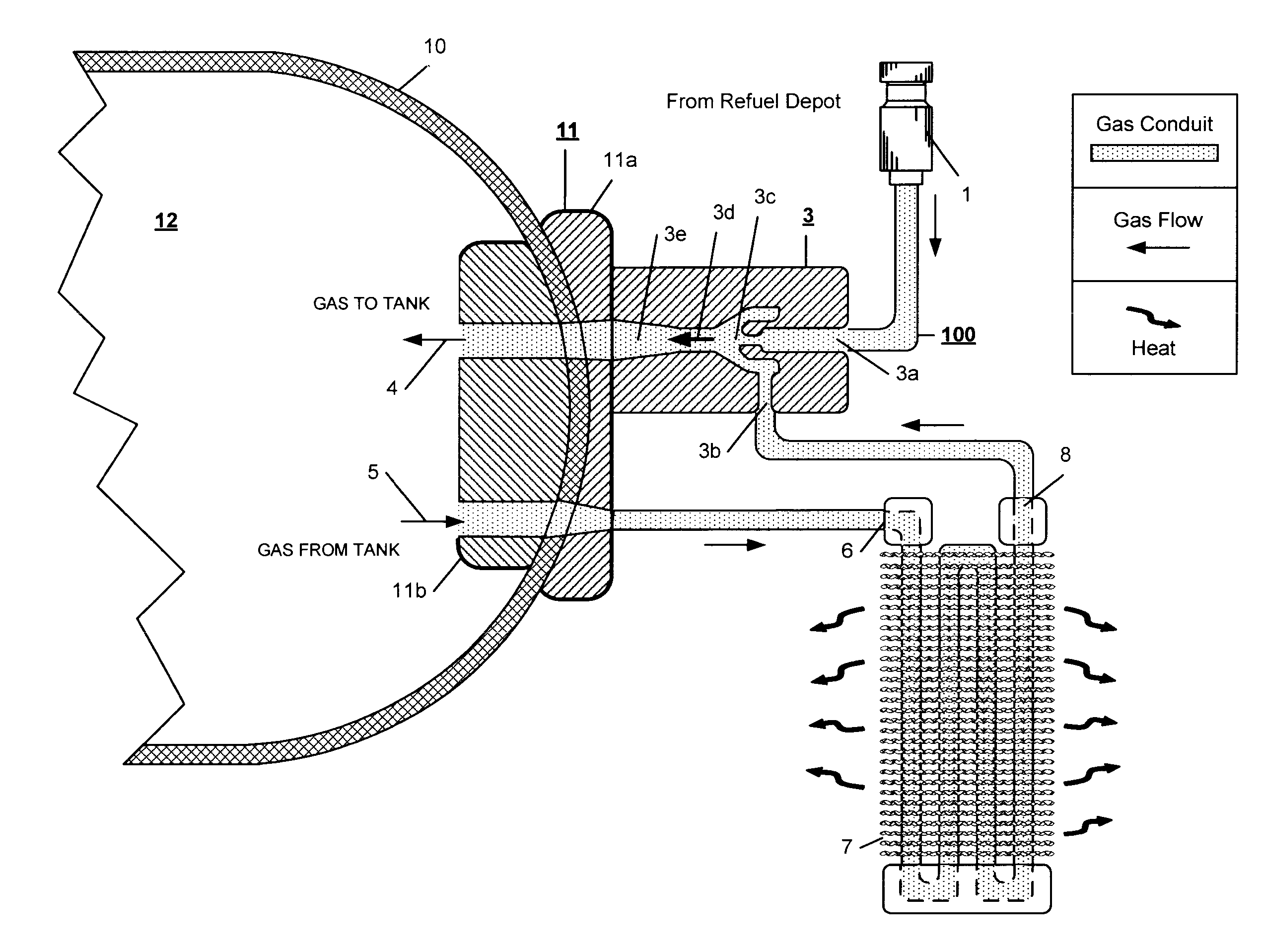
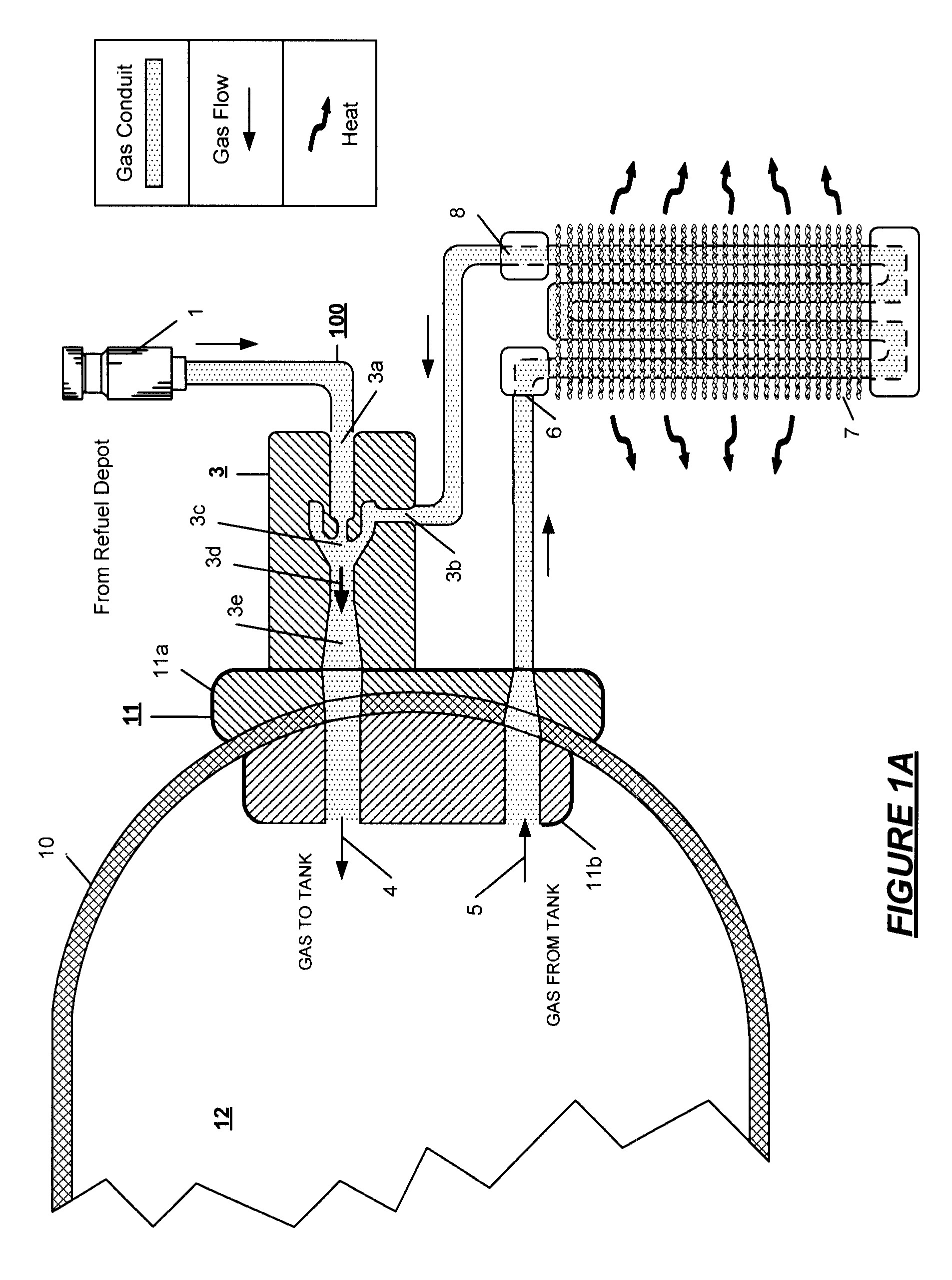
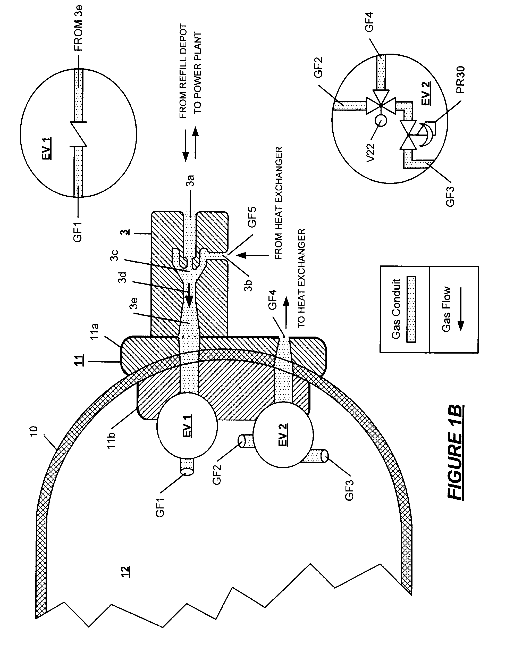
[0028]The system of the invention increases the refueling energy efficiency of hydrogen powered vehicles by withdrawing the heat of refilling compression from the high pressure gas introduced into on board tanks and by eliminating the need for a slow fill, a pressure overfill and / or refueling station precooling of the gas. The refueling gas is introduced into an ejector pump that sucks out the hot gas from the tank interior; the hot gas transits through a heat exchanger where the gas is cooled down. Afterwards, the cooler gas and the refueling gas are mixed in the ejector and then introduced into the storage tank.

[0029]As a result, overall high pressure gas infrastructure energy requirements for motor vehicles are reduced, vehicle mileage range is increased, reducing the need for short interval refills, weight and cost are reduced, and consumer satisfaction is enhanced.

[0030]With reference to FIG. 1A an example of a cooling system using an ejector pump fixed at one end cap or port a...


PUM

PropertyMeasurementUnit
pressuresaaaaaaaaaa
pressuresaaaaaaaaaa
pressuresaaaaaaaaaa

Abstract

Apparatus wherein the compression heat of refueling of a high pressure storage tank is evacuated from the interior of the tank in which a gas circulating within the tank passes through an ejector pump powered by the mechanical energy of the refueling gas as the gas traverses from the high pressure refuel depot to the storage tank and the circulating gas absorbs the refueling heat and carries the heat to a cooling system before the gas is introduced into the tank for storage.

Description

RELATED APPLICATIONS[0001]This application is a continuation in part of my co-pending applications for United States Letters Patent: Gas Cooling Methods for High Pressure Fuel Storage Tanks on Vehicles Powered by Compressed Natural Gas or Hydrogen, Ser. No. 11 / 279,574 filed on Apr. 13, 2006; Pressure Powered Cooling System for Enhancing the Refill Speed and Capacity of On Board High Pressure Vehicle Gas Storage Tanks, Ser. No. 11 / 380,429 filed on Apr. 27, 2006; Gas Cooling Method Using a Melting / Solidifying Media for High Pressure Storage Tanks for Compressed Natural Gas or Hydrogen, Ser. No. 11 / 381,005 filed on May 1, 2006; and System for Enhancing the Efficiency of High Pressure Storage Tanks for Compressed Natural Gas or Hydrogen, Ser. No. 11 / 380,996 filed on May 1, 2006.FIELD OF THE INVENTION[0002]The present invention relates to a system for efficiently cooling high pressure gas stored in fuel tanks, typically, hydrogen gas and compressed natural gas introduced to the tank at a...

Claims


Application Information

Patent Timeline
Patent Type & Authority Patents(United States)
IPC IPC(8): B65B1/04
CPCF17C5/007F17C13/025F17C13/026F17C5/06Y02E60/324F17C2201/0104F17C2201/056F17C2205/0107F17C2205/0126F17C2205/013F17C2205/0142F17C2205/0176F17C2205/0323F17C2205/0391F17C2205/0397F17C2221/012F17C2221/033F17C2223/0123F17C2223/036F17C2225/0123F17C2225/036F17C2227/0114F17C2227/0339F17C2227/0346F17C2227/0355F17C2227/0388F17C2250/032F17C2250/043F17C2250/0439F17C2260/011F17C2260/021F17C2260/023F17C2260/025F17C2265/066F17C2270/0139F17C2270/0168Y02E60/321Y02E60/32
Inventor HANDA, KIYOSHI
Owner HONDA MOTOR CO LTD
Why Eureka
Try Eureka