
Apparatus for optical stimulation of nerves and other animal tissue

a technology of optical stimulation and apparatus, applied in the field of optical nerve stimulation, can solve the problems of many limitations of electrical, mechanical, chemical, and metal probes used to deliver electrical stimulation to nerves of subjects, and the danger of projectile accidents

Inactive Publication Date: 2010-06-15
NERVESENSE LTD
View PDF108 Cites 81 Cited by
  • Summary
  • Abstract
  • Description
  • Claims
  • Application Information

AI Technical Summary

Benefits of technology

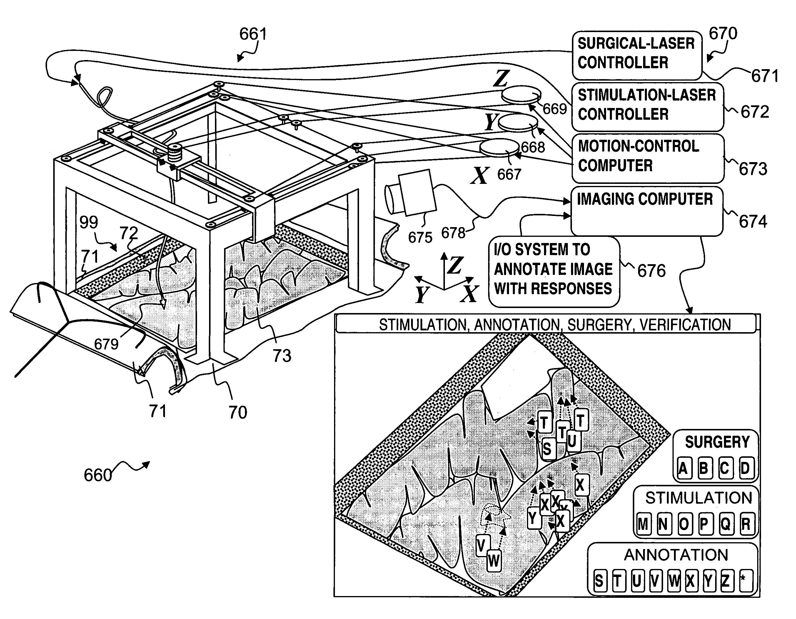
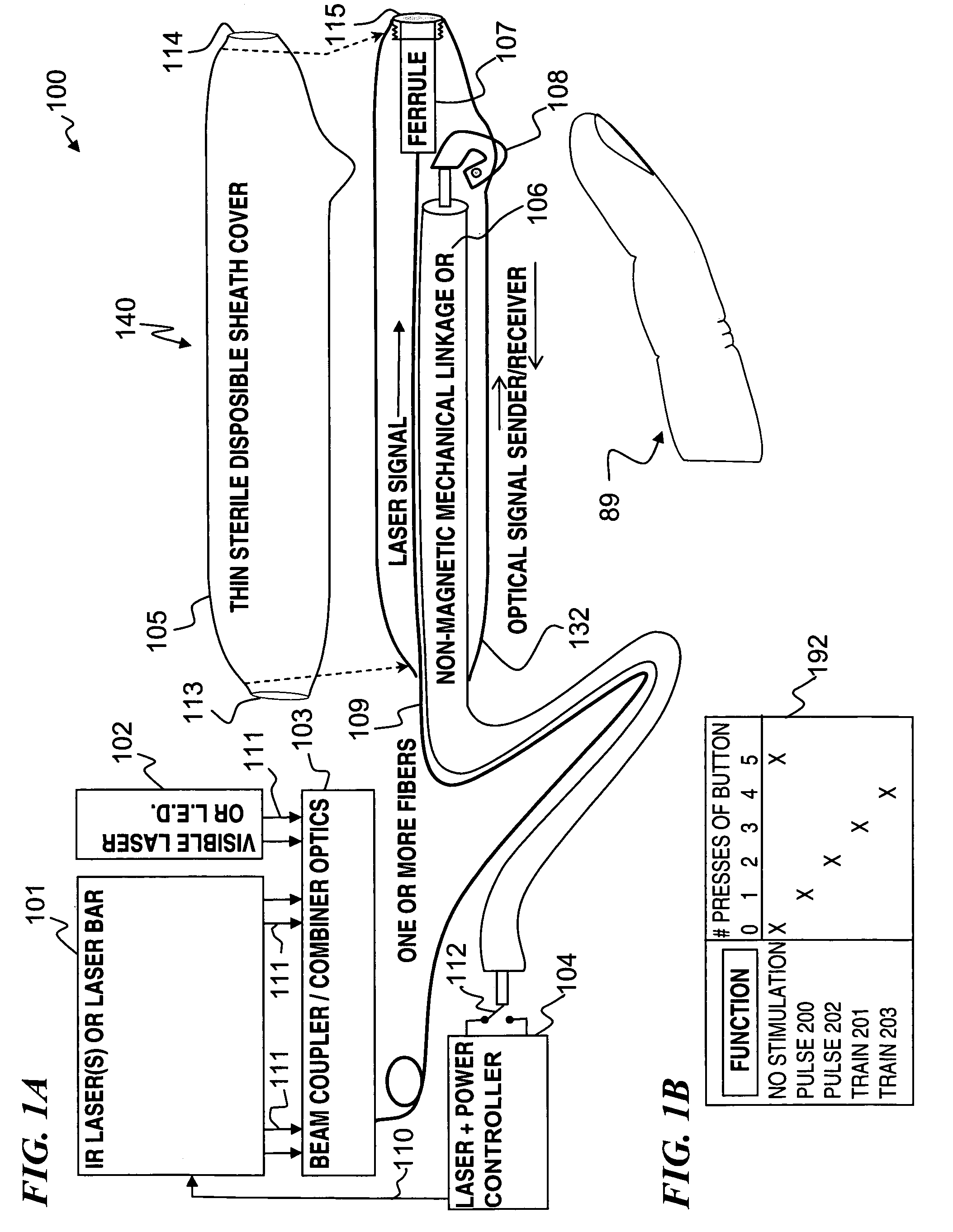
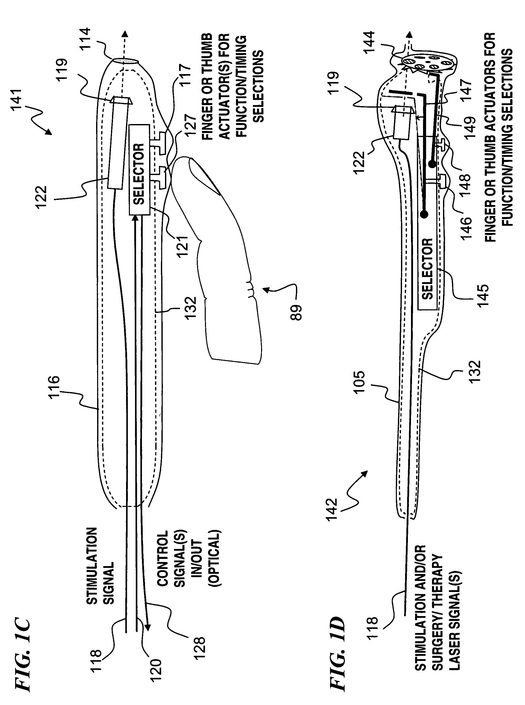
[0012]In some embodiments, the present invention includes at least. some of the following: a first light-emitting source, a second light-emitting source, a light-beam combiner, a mechanical linkage with a trigger mechanism, a ferrule, a light-emitting-source controller, and a disposable sheath. In some embodiments, the sheath includes a lens or other optics to focus the light from the fiber to a particular spot size and / or shape. In some embodiments, a plurality of different interchangeable sheaths are provided, each having a different spot size and / or shape, allowing the surgeon to choose the appropriate light pattern, and / or to change the light pattern based on results of the first-tried sheath's light pattern and the patient response obtained.

Problems solved by technology

The high static magnetic fields (B0 fields) created by an MRI machine create a danger of projectile accidents from any object having magnetic properties that may be near the MRI machine.
Using metal probes to deliver electrical stimulation to nerves of a subject poses one such danger.
Electrical, mechanical, and chemical stimulations have many limitations.
To name a few, stimulation by such methods typically results in non-specific stimulation of neurons and / or damage to neurons.
Difficulty exists in recording electrical activity from the neuron due to an electrical artifact created by the stimulus.
Such techniques do not easily lend themselves to implantable electrodes for long-term use in stimulation of neural tissue.
Unfortunately, FELs are expensive, large, awkward and unwieldy.
Further, conventional optical systems include some magnetic materials, making them unsuitable for use near MRI systems.

Method used


Image

  • Apparatus for optical stimulation of nerves and other animal tissue
  • Apparatus for optical stimulation of nerves and other animal tissue
  • Apparatus for optical stimulation of nerves and other animal tissue

Examples


Embodiment Construction

[0047]Although the following detailed description contains many specifics for the purpose of illustration, a person of ordinary skill in the art will appreciate that many variations and alterations to the following details are within the scope of the invention. Accordingly, the following preferred embodiments of the invention are set forth without any loss of generality to, and without imposing limitations upon the claimed invention.

[0048]In the following detailed description of the preferred embodiments, reference is made to the accompanying drawings that form a part hereof, and in which are shown by way of illustration specific embodiments in which the invention may be practiced. It is understood that other embodiments may be utilized and structural changes may be made without departing from the scope of the present invention.

[0049]The leading digit(s) of reference numbers appearing in the Figures generally corresponds to the Figure number in which that component is first introduc...


PUM


Abstract

A nerve-stimulation device and method using light to provide a source of precise stimulation on one or more nerve fibers. In some embodiments, this simulation is provided through a device and method wherein a laser- or LED-light-generating source is operatively coupled to an optical fiber, which in turn is coupled to a plug in the end of a holder in a sheath. Light is then passed from the light source through the optical fiber to the holder and out a selected optical tip on the sheath to provide an efficacious amount of light to simulate nerves. In some embodiments, the device is constructed from non-magnetic material such as glass, plastic or ceramics. In some embodiments, the light emanating from the optical tip can be controlled manually or automatically. Some embodiments omit the fiber and use light directly from the laser diode.

Description

CROSS-REFERENCE TO RELATED APPLICATIONS[0001]This invention claims benefit of U.S. Provisional Patent Application 60 / 715,884 filed Sep. 9, 2005, titled “Apparatus and Method for Optical Stimulation of Nerves,” which is hereby incorporated by reference in its entirety.FIELD OF THE INVENTION[0002]The invention relates generally to optical nerve stimulation, and more particularly to methods and apparatus to generate, direct, and control the optical signal used to stimulate nerves and other animal tissue, and in particular, neural tissue.BACKGROUND OF THE INVENTION[0003]A nerve can be stimulated in a number of different ways, including electrical, mechanical, thermal, chemical, and now optical. A nerve is a filament of neural tissue composed of cells each having a cell body and one or more axons and dendrites. The axons extend peripherally as either myelinated or unmyelinated fibers. A chain of Schwann cells surrounds each myelinated nerve fiber with a multilayered myelin sheath. Groups...

Claims


Application Information

Patent Timeline
Patent Type & Authority Patents(United States)
IPC IPC(8): A61N5/067
CPCA61N5/0601A61N5/0622A61B18/20A61N2005/067A61B2017/00115A61B2017/00973A61B2018/2065A61B2018/207A61B2018/2075A61N2005/0629A61N2005/063A61N2005/0644A61N2005/0651A61N2005/0659A61B19/5225A61B2017/00384A61B2018/00922A61B2018/00958A61B90/37A61N5/067
Inventor WEBB, JAMES S.HAMILTON, CHARLES E.RALPH, HEATHER A.BENDETT, MARK P.LEMAIRE, CHARLES A.
Owner NERVESENSE LTD
Learn More