Battery packs having a charging mode and a discharging mode

a battery pack and charging mode technology, applied in secondary cell servicing/maintenance, batteries, safety/protection circuits, etc., can solve the problems of large current flow in the battery, dangerous, and overcharging of lithium ion batteries, so as to reduce cost and space, and suppress the influence of radiating noise

Active Publication Date: 2010-06-15
MURATA MFG CO LTD
View PDF24 Cites 60 Cited by
  • Summary
  • Abstract
  • Description
  • Claims
  • Application Information

AI Technical Summary

Benefits of technology

[0019]Therefore, an object of the present invention is to provide a battery pack that has one voltage converter in common with a charging voltage converter and a discharging voltage converter and that allows an electronic device not to have a voltage converting circuit such as a DC-DC converter so as to reduce cost and space and suppress the influence of radiating noise generated from the voltage converting circuit.
[0024]According to the present invention, one voltage converter has a function for a charging voltage converter and a function for a discharging voltage converter and switching means switches one function to the function. Thus, the cost of the battery pack can be reduced in accordance with the structure having both the charging voltage converter and the discharging voltage converter. In addition, an electronic device does not need a voltage converter. Moreover, the electronic device or the battery pack does not need the space for the voltage converter.
[0025]When a DC-DC converter is used as a voltage converter, if it is switched at a high frequency ranging from 10 kHz to 2 MHz, radiating noise takes place. According to the present invention, when the battery pack has a DC-DC converter as a voltage converter, the distance between the internal circuit of the electronic device and the DC-DC converter becomes large. Thus, the influence of noise of the DC-DC converter against the internal circuit of the electronic device can be suppressed. In addition, since the battery pack has a voltage converter, a steel battery case of a box shaped battery or an aluminum laminate film of a lithium polymer battery can reduce noise of radio frequency electromagnetic waves.
[0026]According to the present invention, the secondary battery can be charged with electricity without need to use an AC adaptor and a cradle. In addition, since the AC plug is used in common with a charging input terminal and a discharging output terminal, the number of external terminals can be decreased. In addition, since the battery pack has a discharging voltage converter, the electronic device does not need a discharging voltage converter. As a result, the circuit structure of the electronic device can be simplified. When a DC-DC converter is used and a switching control is preformed at a high frequency of 10 kHz to 2 MHz, radiating noise takes place. When the battery pack has a DC-DC converter as a voltage converter, the distance between the internal circuit of the electronic device and the DC-DC converter can be increased. As a result, the influence of noise against the internal circuit of the electronic device can be suppressed. When the battery pack has a voltage converter, a steel battery case of a box shaped battery or an aluminum laminate film of a lithium polymer battery can suppress noise of high frequency electromagnetic waves.

Problems solved by technology

When the lithium ion battery is overcharged, it may become dangerous.
However, since the charger may become defective and a different type charger may be used, the lithium ion battery may be overcharged.
When the plus terminal and the minus terminal of the lithium ion battery are short-circuited, there is a risk of which a large current flows in the battery and it is abnormally heated up.
Thus, the conventional secondary battery pack is adversely expensive and needs the space for them.
In addition, since the electronic device has the DC-DC converter, there is a risk of which the DC-DC converter generates noise.

Method used


Image

  • Battery packs having a charging mode and a discharging mode
  • Battery packs having a charging mode and a discharging mode
  • Battery packs having a charging mode and a discharging mode

Examples


first embodiment

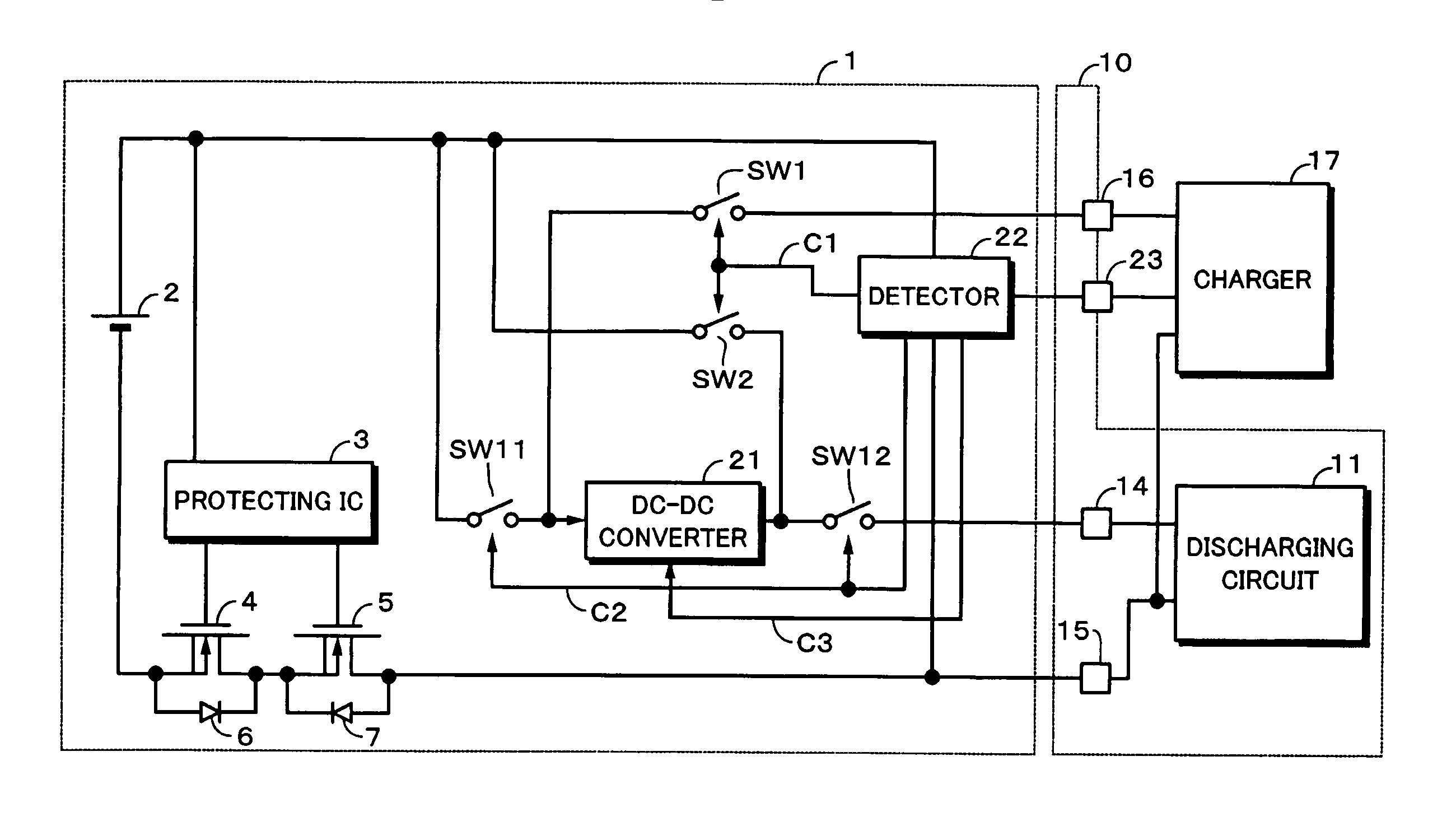
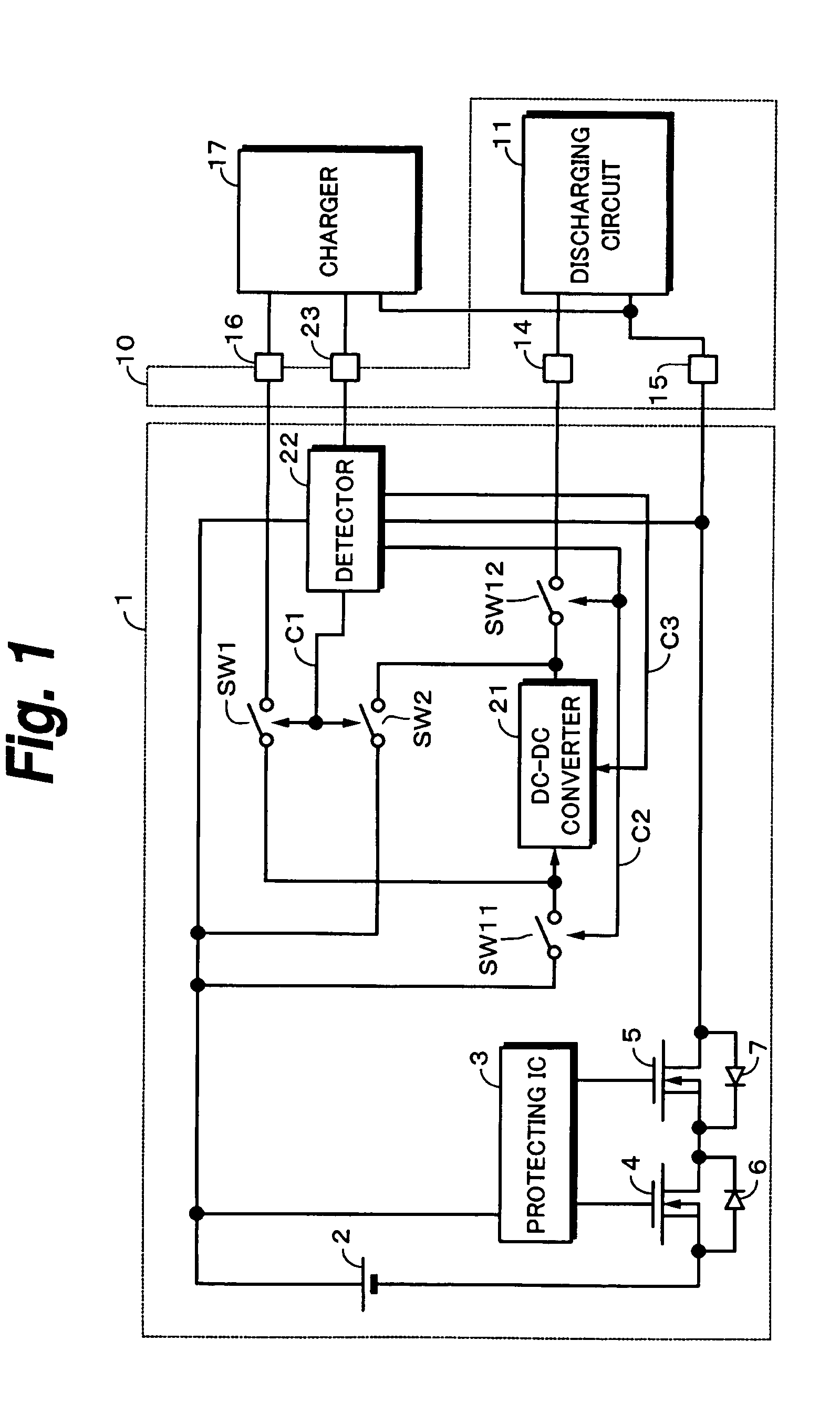
[0062]FIG. 1 shows the structure of a battery pack according to a first embodiment of the present invention. In FIG. 1, similar portions to those described above are denoted by similar reference numerals. In other words, a battery pack 1 has a secondary battery 2 and a protecting circuit 3. A discharging controlling FET 4 and a charging controlling FET 5 are controlled in accordance with an output of the protecting circuit 3. An electronic device 10 has a discharging circuit 11 that needs a DC power supply.

[0063]The discharging circuit 11 is connected to a discharging output terminal 14 and a ground terminal 15. An external charger 17 inputs an AC voltage of 100 V as a home use power supply (commercial power supply) and supplies a charging voltage of for example 5 V to a charging terminal 16 and the ground terminal 15.

[0064]Reference numeral 21 represents a DC-DC converter. Besides the DC-DC converter 21, other DC-DC converters may be disposed so as to obtain a plurality of discharg...

second embodiment

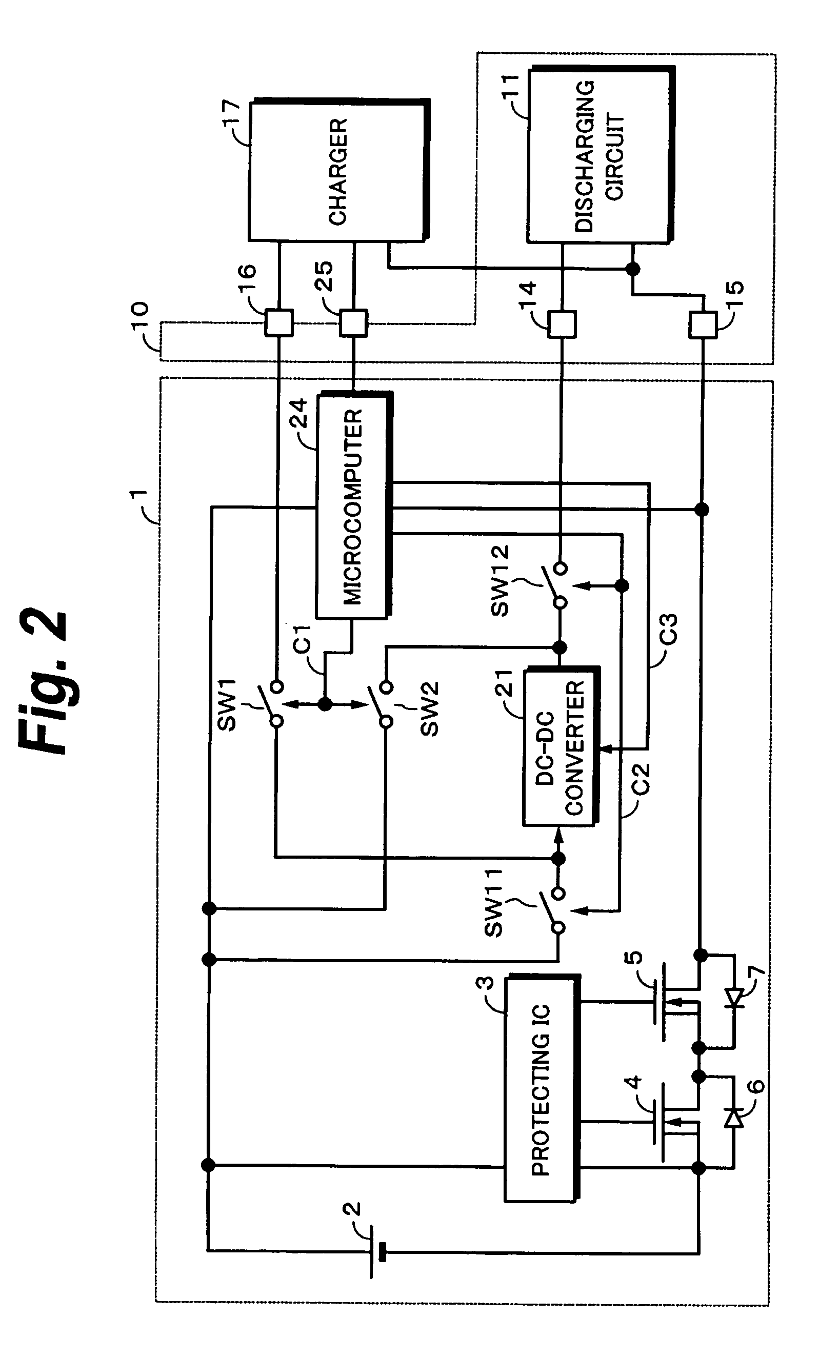
[0070]FIG. 2 shows the structure of a battery pack according to a second embodiment of the present invention. According to the second embodiment, a microcomputer denoted by reference numeral 24 is disposed. The microcomputer 24 generates control signals C1, C2, and C3.

[0071]The microcomputer 24 performs a digital communication with a charger 17 through a communication terminal 25. As a digital communication system, a conventional duplex communication can be used. With the digital communication, the microcomputer 24 determines whether or not a proper charger 17 has been connected to a battery pack 1.

[0072]When a proper charger 17 has not been connected to the battery pack 1, the microcomputer 24 determines that the battery pack 1 should operate in a discharging mode. In other words, the control signals C1, C2, and C3 cause switches SW1 and SW2 to be turned off and switches SW11 and SW12 to be turned on. As a result, an output voltage of the DC-DC converter 21 becomes a preset dischar...

third embodiment

[0074]FIG. 3 shows the structure of a battery pack according to a third embodiment of the present invention. A battery pack according to the third embodiment is denoted by reference numeral 1 and has a mechanical switch 26. When a charger 17 is connected to an electronic device 10, the switch 26 is mechanically turned on (or off). The switch 26 generates a control signal C0.

[0075]When the charger 17 has not been connected, for example the switch 26 is tuned off and the control signal C0 becomes for example “0” (that represents logical “0”). As a result, the battery pack 1 operates in the discharging mode. In other words, the control signal causes switches SW1 and SW2 to be turned off and switches SW11 and SW12 to be turned on. The output voltage of the DC-DC converter 21 becomes the preset discharging output voltage.

[0076]When the charger 17 is connected to the battery pack 1, the switch 26 is turned on and the control signal C0 becomes “1” (that presents logical “1”). As a result, ...


PUM

PropertyMeasurementUnit
constant voltageaaaaaaaaaa
voltageaaaaaaaaaa
frequencyaaaaaaaaaa

Abstract

A battery pack having a secondary battery is disclosed. The battery pack comprises at least one voltage converter; and switching means for switching an operation mode of the voltage converter to one of a charging mode and a discharging mode, in the charging mode, a charging voltage being output to the secondary battery, in the discharging mode, a voltage of the secondary battery being converted into a predetermined discharging voltage and the converted voltage being output.

Description

RELATED APPLICATION DATA[0001]The present application claims priority to Japanese Application(s) No(s). P2003-365 854 filed Oct. 27, 2003, P2003-373052 filed Oct. 31, 2003, and P2003-389277 filed Nov. 19, 2003, which application(s) is / are incorporated herein by reference to the extent permitted by law.BACKGROUND OF THE INVENTION[0002]1. Field of the Invention[0003]The present invention relates to secondary battery packs such as lithium ion batteries and so forth.[0004]2. Description of the Related Art[0005]An electronic device that uses a battery pack requires several types of power supply voltages. Thus, the electronic device has a plurality of voltage converters. The voltage converters are for example DC-DC converters that raise and / or lower voltages and generate a plurality of desired voltages. Likewise, when a secondary battery pack is charged with electricity, an output voltage of a charger (AC adaptor) is raised and / or lowered by the DC-DC converters of the electronic device.[...

Claims


Application Information

Patent Timeline
Patent Type & Authority Patents(United States)
IPC IPC(8): H02J7/00H01M10/44H01M10/46H01M50/202H01M50/269H02J7/10
CPCH01M2/1022H01M10/46H02J7/0068H02J7/0063H02J7/0031Y02E60/10H02J7/00302H02J7/00306H02J7/00304H02J7/00712H01M50/269H01M50/202H01M2220/30
Inventor SENNAMI, HIROMITSUTAKAHASHI, KAZUHIKOMISAWA, DAIKISATO, BUNYAAITA, TAKAYUKI
Owner MURATA MFG CO LTD
Why Eureka
Try Eureka