Method and apparatus for detecting crater end of continuously cast product, and method for producing continuously cast product

a technology of continuous casting and crater end, which is applied in the direction of manufacturing tools, instruments, and foundation moulding equipment, can solve the problems of difficult to perform riveting methods for all varieties of chemical components, known methods, and high cost, and achieves superior absolute measurement, superior relative measurement accuracy, and high accuracy.

Active Publication Date: 2010-06-22
JFE STEEL CORP
View PDF13 Cites 10 Cited by
  • Summary
  • Abstract
  • Description
  • Claims
  • Application Information

AI Technical Summary

Benefits of technology

[0022]The present invention has been made with the view of solving the problems mentioned above, and its object is to provide a method and apparatus for detecting a crater end of a continuously cast product, which can accurately detect the crater end only from a value measured by a sensor without needing calibration based on the slab rivet method, and further to provide a method for producing a continuously cast product, which can improve productivity or quality by utilizing information of the crater end obtained from the method and apparatus for detecting the crater end.
[0027]According to that finding, the method for estimating the crater end by using the ultrasonic longitudinal wave and the method for estimating the crater end based on the heat condition equation, which are superior in accuracy of relative measurement, can be used as a detection means, which is also superior in absolute measurement, by calibrating a calculation formula for computing the crater end, such as the above-mentioned formula (1), or calibrating the values of physical properties used in the calculations based on the heat condition equation on condition that the crater end is matched with the installed position of the ultrasonic shear wave sensor. As another finding confirmed, such a detection method can overcome the problem that, in the case of using only the ultrasonic shear wave, the crater end cannot be measured under the casting conditions where the crater end is positioned downstream of the ultrasonic shear wave sensor in the casting direction.
[0028]In practice, the calculation formula for determining the crater end from the propagation time can be calibrated by deciding the values of physical properties so that the crater end computed from the propagation time measured by the ultrasonic longitudinal wave sensor is matched with the installed position of the ultrasonic shear wave sensor. Similarly, the heat condition equation can be calibrated by performing the calculation based on the heat condition equation under the casting conditions that the crater end is matched with the installed position of an ultrasonic shear wave sensor, and deciding the values of physical properties so that the crater end determined by the calculation based on the heat condition equation is matched with the installed position of the ultrasonic shear wave sensor. Thereafter, by employing the calibrated calculation formula for determining the crater end from the propagation time or the calibrated heat condition equation, it is possible to determine the crater end with high accuracy when the casting conditions are changed, for example, when the casting speed is further increased.

Problems solved by technology

However, those known methods have problems as follows.
Those operations are very troublesome and require a high cost.
Further, it is practically impossible to perform the rivet method for all varieties of chemical components.
For that reason, the method employing the heat condition equation has the problem that an application range is limited and high accuracy cannot be obtained.
Accordingly, it is practically impossible to perform the calibration for all varieties of chemical components as with the above method employing the heat condition equation.
However, because the slab containing a liquid core undergoes bulging, it is also difficult to stably measure the thickness of the slab under casting, thus deteriorating the measurement accuracy.
Therefore, the crater end cannot be detected by installing only one pair of the transmitter and the receiver, and many pairs of the transmitter and the receiver must be installed in the casting direction to detect the crater end.
However, when the crater end is positioned downstream of the installed position of the transmitter and the receiver, an ultrasonic passage signal cannot be obtained by the method using the ultrasonic shear wave, and hence the crater end cannot be detected.

Method used


Image

  • Method and apparatus for detecting crater end of continuously cast product, and method for producing continuously cast product
  • Method and apparatus for detecting crater end of continuously cast product, and method for producing continuously cast product
  • Method and apparatus for detecting crater end of continuously cast product, and method for producing continuously cast product

Examples


first embodiment

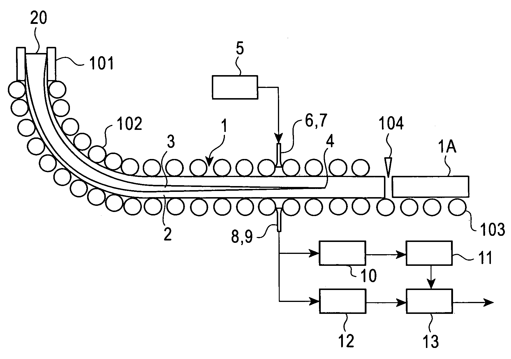
[0069]The present invention will be described in detail below with reference to the accompanying drawings. A method and apparatus for directly detecting a crater end from the propagation time of an ultrasonic longitudinal wave signal measured by an ultrasonic longitudinal wave sensor will be first described. FIG. 1 shows the present invention related to the method and apparatus for directly detecting the crater end from the propagation time of the ultrasonic longitudinal wave signal measured by the ultrasonic longitudinal wave sensor. In other words, FIG. 1 is a schematic view of a slab continuous casting machine provided with a crater end detector according to the present invention, in which an ultrasonic shear wave sensor and the ultrasonic longitudinal wave sensor are installed at the same position in the continuous casting machine.

[0070]In FIG. 1, reference numeral 1 denotes a cast product (slab), 2 denotes a solid phase, 3 denotes a liquid phase, and 4 denotes a crater end. Mol...

second embodiment

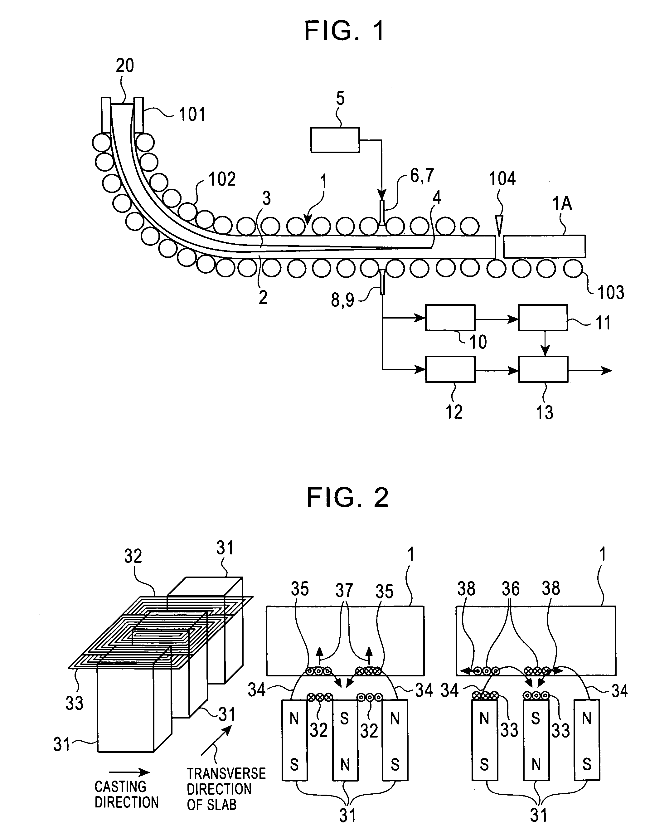
[0099]In the second embodiment, as shown in FIG. 8, the ultrasonic shear wave sensor made up of the ultrasonic shear wave transmitter 6 and the ultrasonic shear wave receiver 8 and the ultrasonic longitudinal wave sensor made up of the ultrasonic longitudinal wave transmitter 7 and the ultrasonic longitudinal wave receiver 9 are separately disposed in two points apart from each other in the casting direction. In this case, the ultrasonic shear wave sensor and the ultrasonic longitudinal wave sensor are not required to be the above-described sensor for generating and detecting the ultrasonic longitudinal wave and the ultrasonic shear wave at the same position, shown in FIG. 2, and can be each constituted as an ordinary electromagnetic ultrasonic sensor. Of course, the electromagnetic ultrasonic sensor shown in FIG. 2 can also be employed.

[0100]However, since the crater end 4 sometimes differs in the transverse direction of the slab 1 in the slab continuous casting machine, the ultras...

fourth embodiment

[0114]The method and apparatus for detecting the crater end from the casting conditions and the values of physical properties by calculation based on the heat condition equation will be described below. FIG. 11 shows the present invention, and it is a schematic view of a slab continuous casting machine provided with a crater end detector according to the present invention.

[0115]The crater end detector according to the present invention for detecting the crater end 4 from the casting conditions and the values of physical properties by calculation based on the heat condition equation comprises, as shown in FIG. 11, an ultrasonic shear wave sensor made up of an ultrasonic shear wave transmitter 6 and an ultrasonic shear wave receiver 8 disposed in opposed relation with a slab 1 between them, an ultrasonic transmitting unit 5 which is an electric circuit for supplying an electric signal to the ultrasonic shear wave transmitter 6, thereby causing an ultrasonic wave to be transmitted to t...


PUM

PropertyMeasurementUnit
magnetic fieldaaaaaaaaaa
currentaaaaaaaaaa
voltageaaaaaaaaaa

Abstract

A method for detecting a crater end of a continuously cast product including installing an ultrasonic shear wave sensor for transmitting an ultrasonic shear wave to a cast product and receiving the transmitted ultrasonic longitudinal wave and an ultrasonic longitudinal wave sensor for transmitting an ultrasonic longitudinal wave to the cast product and receiving the transmitted ultrasonic longitudinal wave at the same position in a continuous casting machine or at positions apart from each other in a casting direction, but at the same position in a transverse direction of the cast product, detecting based on variations of an ultrasonic signal received by the ultrasonic shear wave sensor that the crater end of the cast product is matched with the installed position of the ultrasonic shear wave sensor, calibrating a calculation formula for determining the crater end and determining the crater end.

Description

[0001]This application is the United States national phase application of International Application PCT / JP2004 / 017824 filed Nov. 24, 2004.TECHNICAL FIELD[0002]The present invention relates to a method and apparatus for detecting a crater end of a continuously cast product online, which is under a casting process in a continuous casting machine, and also relates to a method for producing a continuously cast product.BACKGROUND ART[0003]In continuous casting of steel, it is very important to determine at which position in a continuously cast product is completed solidification of the continuously cast product (hereinafter referred to as a “crater end”). The reason is that detection of the crater end contributes to greatly improving productivity and quality of the cast product.[0004]For example, when the casting speed is increased to improve productivity, the crater end is moved downstream in the casting direction of the cast product. If the crater end exceeds the range of rolls support...

Claims


Application Information

Patent Timeline
Patent Type & Authority Patents(United States)
IPC IPC(8): B22D11/00B22D11/16
CPCB22D11/16G01N2291/02881B22D11/186G01N29/024H01F7/02
Inventor IIZUKA, YUKINORIKUBOTA, JUNTSUTSUMI, KOICHI
Owner JFE STEEL CORP
Why Eureka
Try Eureka