Travel control device and method for vehicles

a technology for controlling devices and vehicles, applied in the direction of distance measurement, navigation instruments, instruments, etc., can solve the problems of reducing the efficiency and work efficiency of conveyancing, the inability of vehicles to continue high-speed traveling without, and the practicability of making all vehicles traveling in the work area unmanned

Active Publication Date: 2010-06-22
KOMATSU LTD
View PDF10 Cites 21 Cited by
  • Summary
  • Abstract
  • Description
  • Claims
  • Application Information

AI Technical Summary

Benefits of technology

[0021]The present invention is contrived in view of such circumstances, and an object thereof is to securely ensure the safety and improve the conveyance efficiency and work efficiency by, when vehicles proceed towards each other from the opposite directions, a vehicle traveling behind is caused to bypass the front car (work vehicle, slowly-moving vehicle, disabled vehicle, or the like) at high speed because the front car is an obstacle to high-speed travel of the vehicle behind, while preventing the occurrence of interference between the both vehicles.
[0028]According to a seventh aspect of the present invention, there is provided a travel control method for a vehicle, which causes unmanned vehicles, which are provided with travel control means for causing the vehicle to travel along an instructed traveling course in accordance with data on the instructed traveling course, to travel toward each other from opposite directions on a traveling road having adjacent outward / return lanes, the travel control method comprising the steps of creating a restricted area that surrounds one of the vehicles on either one of the outward / return lanes, on the basis of positional information of the vehicle; creating, on the basis of the restricted area, a detour course which avoids the restricted area, passes the opposite lane, and returns to the original lane of the vehicle; and performing control so as to cause the vehicle to travel along an instructed detour course in accordance with data on the detour course, by informing each of the vehicles of the information on the detour course.
[0029]In the first aspect of the invention, as shown in FIG. 4, a restricted area 60 is created based on positional information 60A, 60B of a manned vehicle 20 traveling one side of inbound / outbound lanes 51, 52 (line 51), and a detour course 72 is created based on the information of the restricted area 60. Information on the detour course 72 is provided to each of unmanned vehicles 10, 11 and the manned vehicle 20. Then, on the basis of positional information of the unmanned vehicle 10 and unmanned vehicle 11 which proceed towards each other from the opposite directions with the restricted area 60 therebetween, the unmanned vehicle 11 on the lane 52 which is the opposite side of the restricted area 60 is blocked by a block position 61B and at the same time a travel permission command for permitting traveling the detour course 72 is issued to the unmanned vehicle 10 traveling the lane 51 on the restricted area 60 side so that the unmanned vehicle 10 travels the detour course 72. Therefore, according to the present invention, when the unmanned vehicle 10 and unmanned vehicle 11 are caused to proceed towards each other from the opposite directions, the occurrence of interference therebetween can be prevented securely, and at the same time the manned vehicle 20 or slowly-moving vehicle, which is an obstacle to high-speed travel of the vehicle 10 behind, can be bypassed at high speed, whereby the conveyance efficiency and work efficiency can be improved while securely ensuring the safety.
[0034]In the sixth aspect of the invention, as shown in FIG. 4, the vehicle existing in the restricted area 60 is the manned vehicle 20, and the travel permission command is issued to the unmanned vehicle 10 traveling the lane 51 on the restricted area 60 side, under the condition that an authorization command for authorizing traveling the detour course 72 is received from the manned vehicle 20. Accordingly, the authorization command is provided from the manned vehicle 20 at the point of time when there is no more probability of straying off the restricted area 60, thus the manned vehicle 20 is securely prevented from interfering with the unmanned vehicle 10.

Problems solved by technology

However, it is practically impossible to make all vehicles traveling in the work area unmanned.
Supposing, for example, that a manned motor grader T3 carries out a road construction on one side of the inbound / outbound traffic lanes, e.g. the traffic lane Ra, the road construction is performed at low speed or in a state in which the motor grader T3 is stopped, and thus impedes high-speed running of the vehicle T1 traveling behind on the same traffic lane Ra, thereby causing a reduction in the conveyance efficiency and work efficiency.
Therefore, it is impossible for the vehicles to continue high-speed traveling without causing interference between the vehicles, unless some sort of control is added thereto.
Consequently, passing the grader T3 cannot be achieved.
Therefore, in some cases, there occurs a problem in which the vehicle T1 runs on to the windrow when passing the grader T3.
As described above, in any of the conventional technologies described above, although the occurrence of interference between vehicles can be prevented, passing a vehicle at high speed cannot be achieved, or although passing a vehicle at high speed can be achieved, the occurrence of interference between vehicles cannot be prevented, thus the conventional technologies could not satisfy such cases.

Method used


Image

  • Travel control device and method for vehicles
  • Travel control device and method for vehicles
  • Travel control device and method for vehicles

Examples


first embodiment

Detouring when a Manned Vehicle is Carrying Out a Work

[0078]Hereinafter, a procedure of a process in the embodiment is described with reference to FIGS. 4A, 4B, 4C, 4D showing the traveling path 50, and the flowchart shown in FIG. 5.

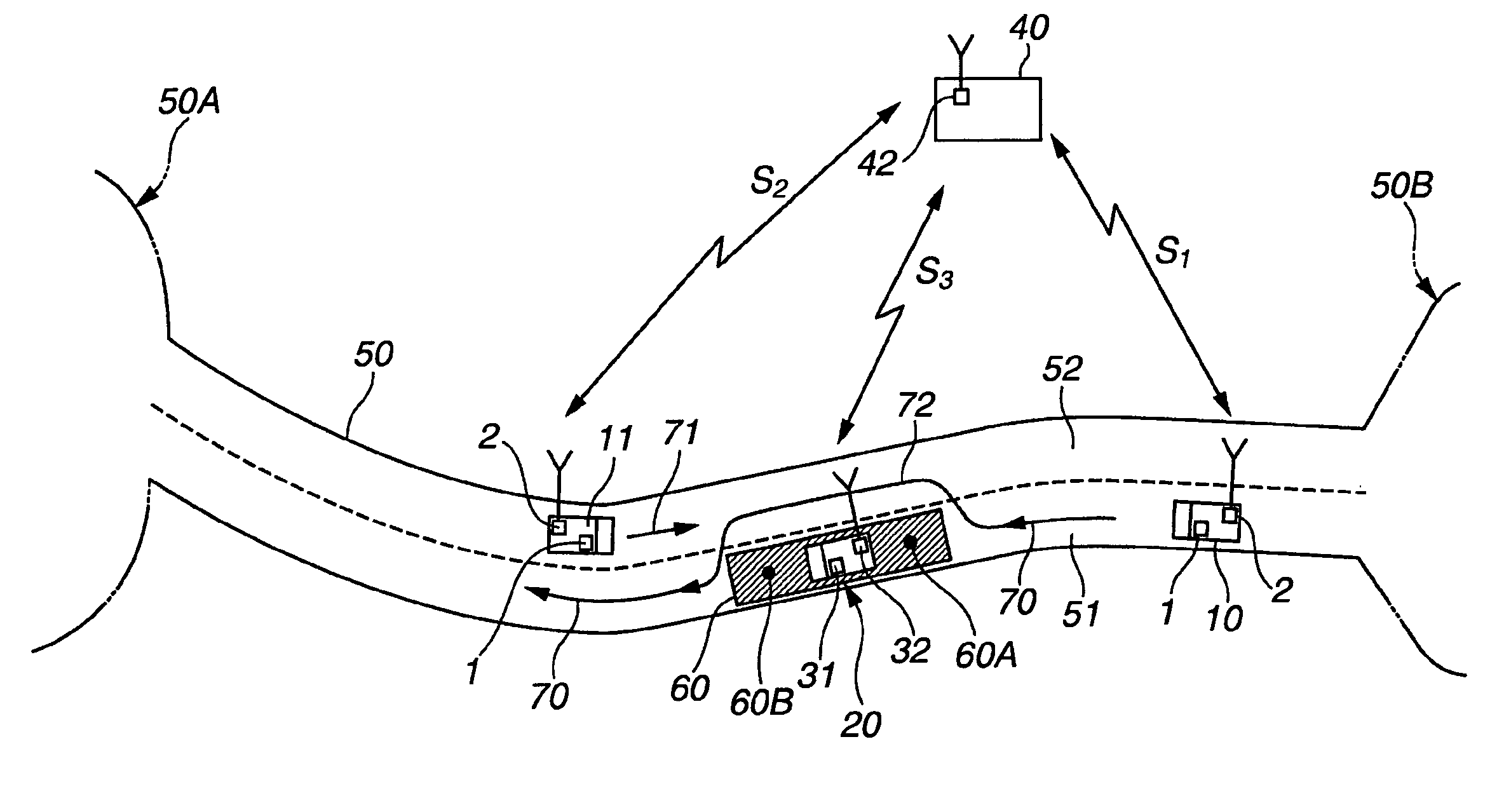
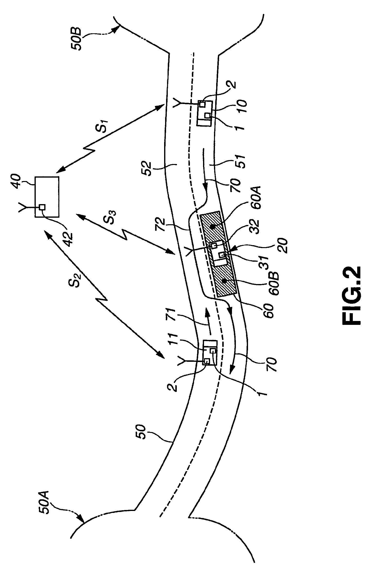
[0079]This embodiment assumes the case in which the manned vehicle 20 carries out a road construction or the like on the traveling road 50.

[0080]First of all, before starting the work on a mine, map data of the traveling road 50 is inputted from the input device 46 of the monitor station 40 and stored in the operation data sharing device 43. This map data includes data showing the terrain of a position of a shoulder of the traveling road 50 or other terrain. The map data of the traveling road 50 is transmitted to all of the unmanned vehicles 10, 11 via the communication device 42 of the monitor station 40 by means of the wireless communications S1, S2 received by the communication device 2 of each of the unmanned vehicles 10, 11 and stored in the operati...

second embodiment

Detouring when a Manned Vehicle is Traveling at Low Speed

[0125]Hereinafter, a procedure of a process in the embodiment is described with reference the configuration diagrams of FIGS. 6A, 6B, 6C, FIGS. 7A, 7B, 7C, 7D showing the traveling path 50, and the flowcharts shown in FIGS. 8 and 9.

[0126]Each of FIGS. 6A, 6B, 6C corresponds to each of FIGS. 3A, 3B, 3C and the reference numerals in FIG. 6 indicate the same components, thus the explanations thereof are omitted accordingly.

[0127]However, as shown in FIG. 6A, the manned vehicle 20 is provided with a passing controller 35′ instead of the restricted area controller 35.

[0128]Moreover, the monitor station 40 is not provided with the input device 46 or display device 47 shown in FIG. 3B, but is provided with the passing controller 45′ instead of the restricted area controller 45.

[0129]The configurations of the unmanned vehicles 10, 11 are same as those shown in FIG. 3C.

[0130]This embodiment assumes a case in which the manned vehicle 20...

third embodiment

Detouring when an Unmanned Vehicle is Traveling at Low Speed

[0177]Hereinafter, a procedure of a process in the embodiment is described with reference the configuration diagrams of FIGS. 10A, 10B, 10C and FIGS. 11A, 11B, 11C showing the traveling path 50.

[0178]In this embodiment, the manned vehicle 20 traveling at low speed in the second embodiment is replaced with an unmanned vehicle 12 traveling at low speed, thus the explanations which overlap with those of the second embodiment are omitted.

[0179]FIGS. 10 A, 10B, 10C correspond to FIGS. 6A, 6B, 6C. The reference numerals in FIGS. 6A, 6B, 6C indicate the same components, thus the explanations thereof are omitted accordingly.

[0180]The configurations of the unmanned vehicles 10, 11 are same as the configuration shown in FIG. 6C of the second embodiment, as shown in FIG. 10C.

[0181]The configuration of the slow unmanned vehicle 12 to be passed is same as the configurations of other unmanned vehicles 10, 11 (FIG. 10C), as shown in FIG. ...


PUM


Abstract

A restricted area (60) is created based on positional information of a manned vehicle (20) traveling one of outward / return lanes (51, 52), and a detour course (72) is created based on information of the restricted area (60). Information on the detour course (72) is provided to the unmanned vehicles (10, 11) and the manned vehicle (20). Based on the positional information of the unmanned vehicles (10, 11) which proceed towards each other from the opposite directions with the restricted area (60) therebetween, the unmanned vehicle (11) on the lane (52) which is the opposite side of the restricted area (60) is blocked at a block position (61B) and at the same time a travel permission command for permitting traveling the detour course (72) is issued to the unmanned vehicle (10) traveling the lane (51) on the restricted area side so that the unmanned vehicle (10) travels the detour course (72).

Description

BACKGROUND OF THE INVENTION[0001]1. Field of the Invention[0002]The present invention relates to travel control device and method for vehicles for causing unmanned vehicles, which are equipped with travel control means for moving the vehicles along a directed traveling course according to the data of the traveling course, to proceed towards each other from the opposite directions on a traveling road having adjacent outward / return traffic lanes.[0003]2. Description of the Related Art[0004]When conveying the earth and sand deposited in a quarry, mine, or other large work area, in order to avoid accidents caused by fatigue of a worker, to achieve downsizing of manpower, and to improve the productivity by extending the work hours, there is introduced an unmanned vehicle travel system for activating unmanned vehicles instead of manned vehicles such as off-road dump trucks. The unmanned vehicle travel system is constructed such that, in order to manage the operation of plural unmanned dum...

Claims


Application Information

Patent Timeline
Patent Type & Authority Patents(United States)
IPC IPC(8): G01C21/26G05D1/02
CPCG05D1/0221G01C21/005G05D1/0297G05D2201/021
Inventor MORI, MASAKISUDOU, TSUGIONISHIJIMA, AKIHARUTOJIMA, MASANORIKUROMOTO, KAZUNORITAKEDA, KOJIOZAKI, TOMONORI
Owner KOMATSU LTD
Why Eureka
Try Eureka