Linearized differential transimpedance amplifier

a technology of differential transimpedance amplifier and linearization, which is applied in differential amplifiers, amplifiers with only semiconductor devices, amplifier details, etc., can solve problems such as inability to introduce unacceptable noise levels in future systems, and achieve adequate operating headroom, reduce sensitivity, and common mode magnitude

Active Publication Date: 2010-06-29
QORVO US INC
View PDF1 Cites 7 Cited by
  • Summary
  • Abstract
  • Description
  • Claims
  • Application Information

AI Technical Summary

Benefits of technology

[0015]The feedback resistors have both input ends and output ends. The diverted common mode currents may be taken from the input ends, the output ends, or both. When a common mode magnitude of the differential input signals is large, such as in an optical overload power condition, the detected magnitude associated with the differential input signals is large. Therefore, the diverted common mode currents are large and may keep the voltage across the feedback resistors in a linear operating region. Likewise, as the common mode magnitude diminishes, the dynamic current source circuitry may be dynamically reconfigured to reduce the diverted common mode currents and keep the voltage across the feedback resistors in the linear operating region by preserving adequate operating headroom and providing sufficient voltage for adequate sensitivity.
[0016]In some embodiments of the present invention, the diverted common mode currents are taken from both the input ends and the output ends of the feedback resistors. The diverted common mode currents taken from the input ends may be dynamically controlled separately from the diverted common mode currents taken from the output ends to trade-off certain characteristics at different common mode magnitudes of the differential input signals. In general, diverted common mode currents taken from the input ends preserve operating headroom, but at the expense of reduced sensitivity and increased input noise. Diverted common mode currents taken from the output ends preserve operating headroom up to point, with less reduced sensitivity and less increased input noise compared to diverted common mode currents taken from the input ends.
[0017]For example, when the common mode magnitude of the differential input signals is small, diverted common mode currents taken from both the input ends and the output ends may be very small, or zero, for maximum sensitivity. As the common mode magnitude of the differential input signals increases, the diverted common mode currents taken from the output ends may increase and the diverted common mode currents taken from the input ends may remain very small, or zero, to preserve sensitivity and minimize shot noise associated with the diverted common mode currents taken from the input ends. As the common mode magnitude of the differential input signals becomes sufficiently large, the diverted common mode currents taken from both the output ends and the input ends may increase to preserve adequate operating headroom, while maintaining adequate sensitivity and keeping shot noise sufficiently small.

Problems solved by technology

However, such amplifiers typically have 50 ohm input resistors, which may introduce unacceptable levels of noise in future systems. FIG. 1 shows a differential limiting amplifier 10 according to the prior art.

Method used


Image

  • Linearized differential transimpedance amplifier
  • Linearized differential transimpedance amplifier
  • Linearized differential transimpedance amplifier

Examples


Embodiment Construction

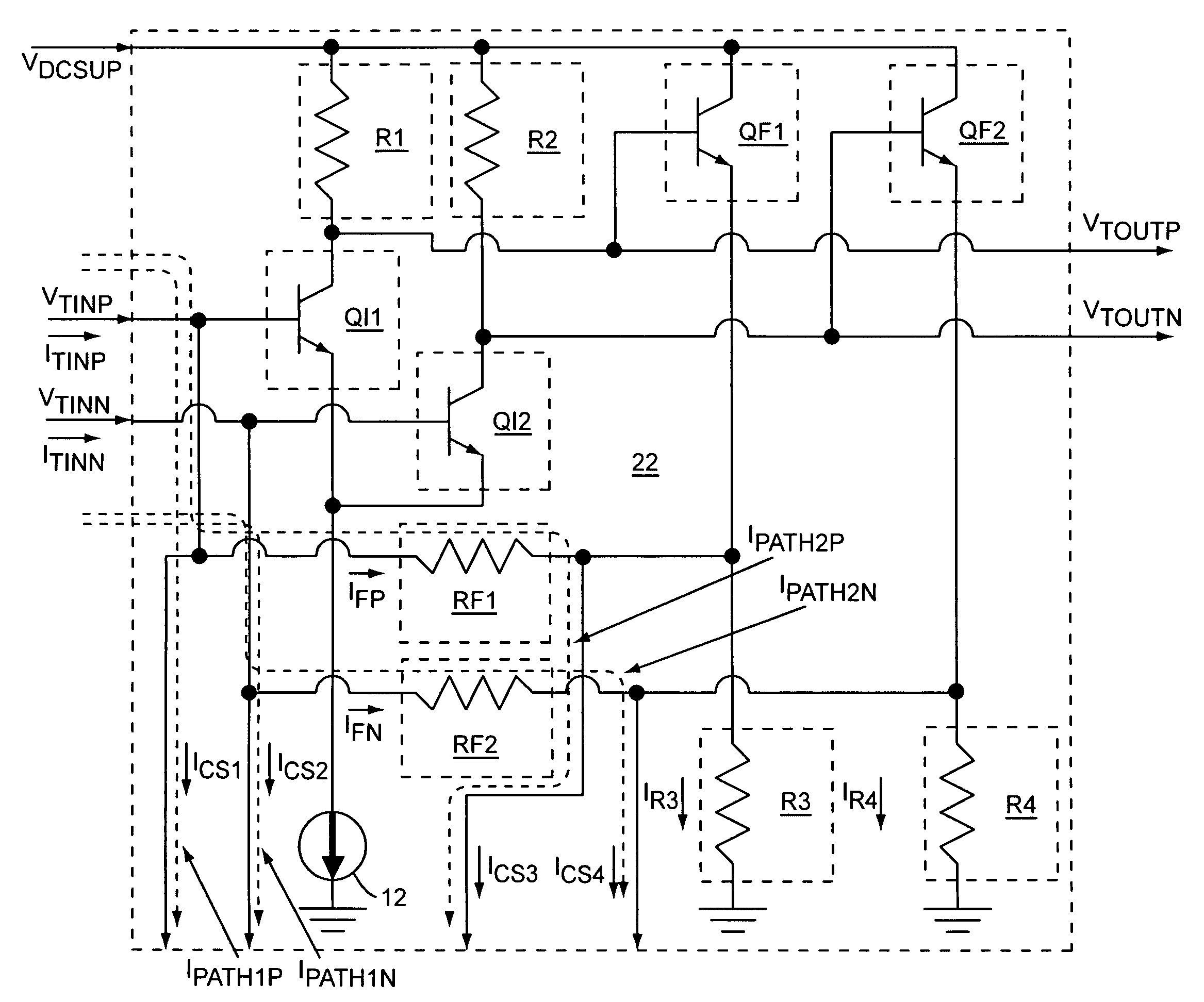
[0014]The present invention relates to a transimpedance amplifier circuit that includes a linearized differential transimpedance amplifier, a detector, and dynamic current source circuitry, which diverts common mode currents from feedback resistors in the linearized differential transimpedance amplifier to keep the linearized differential transimpedance amplifier in a linear operating range. Magnitudes of the diverted common mode currents from the feedback resistors may be based on a detected magnitude associated with differential input signals that feed the linearized differential transimpedance amplifier. The detector provides a detector output signal to the dynamic current source circuitry based on the detected magnitude associated with the differential input signals, such that the diverted common mode currents are based on the detector output signal. The transimpedance amplifier circuit provides differential output signals that are based on amplifying the differential input sign...


PUM


Abstract

The present invention relates to a transimpedance amplifier circuit that includes a linearized differential transimpedance amplifier, a detector, and dynamic current source circuitry, which diverts common mode currents from feedback resistors in the linearized differential transimpedance amplifier to keep the linearized differential transimpedance amplifier in a linear operating range. Magnitudes of the diverted common mode currents from the feedback resistors may be based on a detected magnitude associated with differential input signals that feed the linearized differential transimpedance amplifier. The detector provides a detector output signal to the dynamic current source circuitry based on the detected magnitude associated with the differential input signals, such that the diverted common mode currents are based on the detector output signal. The transimpedance amplifier circuit provides differential output signals that are based on amplifying the differential input signals.

Description

[0001]This application claims the benefit of provisional patent application Ser. No. 61 / 076,061, filed Jun. 26, 2008, the disclosure of which is hereby incorporated herein by reference in its entirety.FIELD OF THE INVENTION[0002]Embodiments of the present invention relate to differential transimpedance amplifiers, which may be used in fiber-optics based communications systems.BACKGROUND OF THE INVENTION[0003]A differential transimpedance amplifier is commonly used to convert a differential input current to a differential output voltage. For example, in a fiber-optics based communications system, photo-diodes in an optical receiver may provide differential output currents based on received optical data. A differential transimpedance amplifier may be coupled to the photo-diodes to convert the differential output currents into differential output voltages. As fiber-optics based communications standards evolve, reach requirements will increase, which will require optical receivers with ...

Claims


Application Information

Patent Timeline
Patent Type & Authority Patents(United States)
IPC IPC(8): H03F3/45
CPCH03F1/083H03F3/08H03F3/45085H03F3/45569H03F2200/411H03F2203/45352H03F2203/45702H03F2203/45722
Inventor KOBAYASHI, KEVIN W.
Owner QORVO US INC
Why Eureka
Try Eureka