Work holding mechanism

a technology of work holding mechanism and work, which is applied in the direction of hoisting equipment, furnace, charge manipulation, etc., can solve the problems of complex mechanical structure, material handling/transport equipment cannot be used in vacuum environment, and the difficulty of weight reduction and simplification as an entire work holding mechanism

Active Publication Date: 2010-07-06
DAIHEN CORP
View PDF9 Cites 390 Cited by
  • Summary
  • Abstract
  • Description
  • Claims
  • Application Information

AI Technical Summary

Benefits of technology

[0007]The present invention has been proposed under the above-described circumstances. It is therefore an object of the present invention to provide a work holding mechanism that is light and simple but capable of operating in a vacuum and preventing the sliding or any other positional deviation of the work during transport to contribute to increasing the transport speed.
[0009]According to the above arrangement, when a work is placed on the base member, part of the work's perimeter, i.e. part of the work's lower surface, makes contact with the contact portions of the guide members. The contact portion in each of the guide members receives the weight of the work, and causes the guide member to turn or pivot about the shaft. This automatically brings the limit portions of the respective guide members to a position to prevent the work from shifting sideways, thereby attaining accurate positioning of the work. According to the work holding mechanism provided by the present invention, the guide members are configured to make a simple movement caused by the weight of the work, and applicable even in a vacuum. Such a guide member is very small in weight and simple in structure. The work holding mechanism according to the present invention reliably prevents lateral shift of the work being transported, which contributes to improvement in transportation speed.
[0017]With the above arrangement, the attachment of the guide members to the base member is attained easily by putting the shaft of each guide member into the groove. Further, the off-center arrangement of the shaft allows the guide members to assume an appropriately tilted position in a natural state.
[0019]With the above arrangement, determination of whether or not the work is on the base member is easily performed.

Problems solved by technology

However, the conventional work holding mechanism uses an air cylinder to move the clamp pawls, so there is a problem that the material handling / transport equipment cannot be used under vacuum environment.
Further, the actuator for moving the clamp pawls employs a large number of different parts, resulting in a complex mechanical structure and a difficulty in weight reduction and simplification as an entire work holding mechanism.

Method used


Image

  • Work holding mechanism
  • Work holding mechanism
  • Work holding mechanism

Examples


Embodiment Construction

[0026]Preferred embodiments of the present invention will be described below with reference to the accompanying drawings.

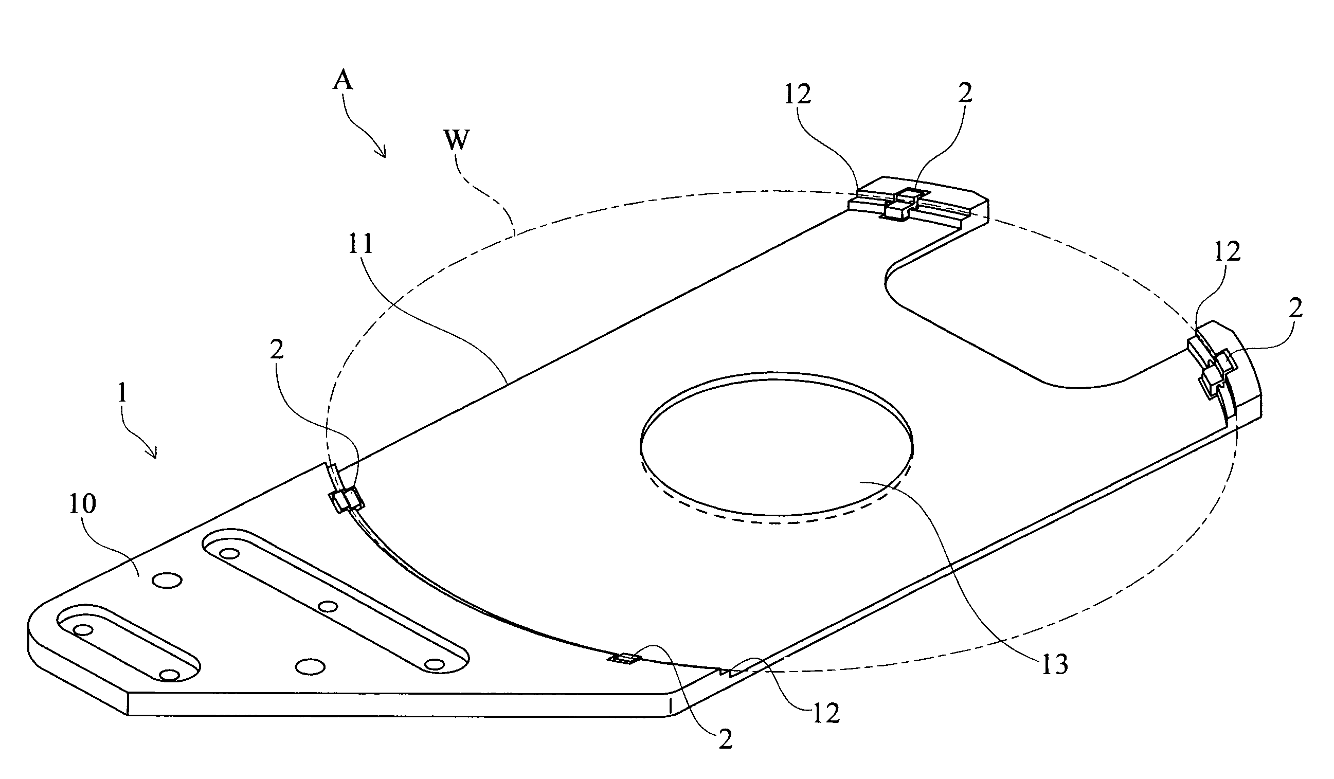
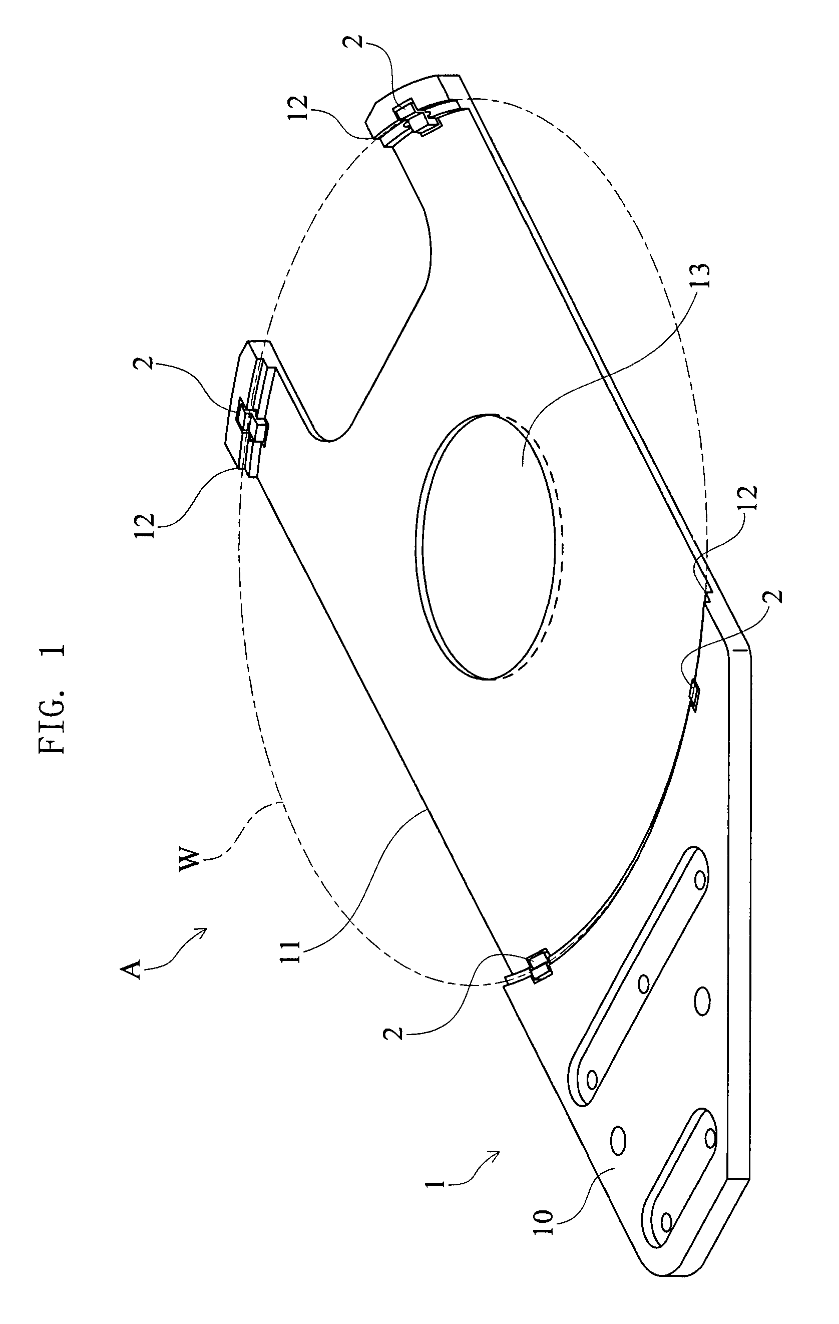
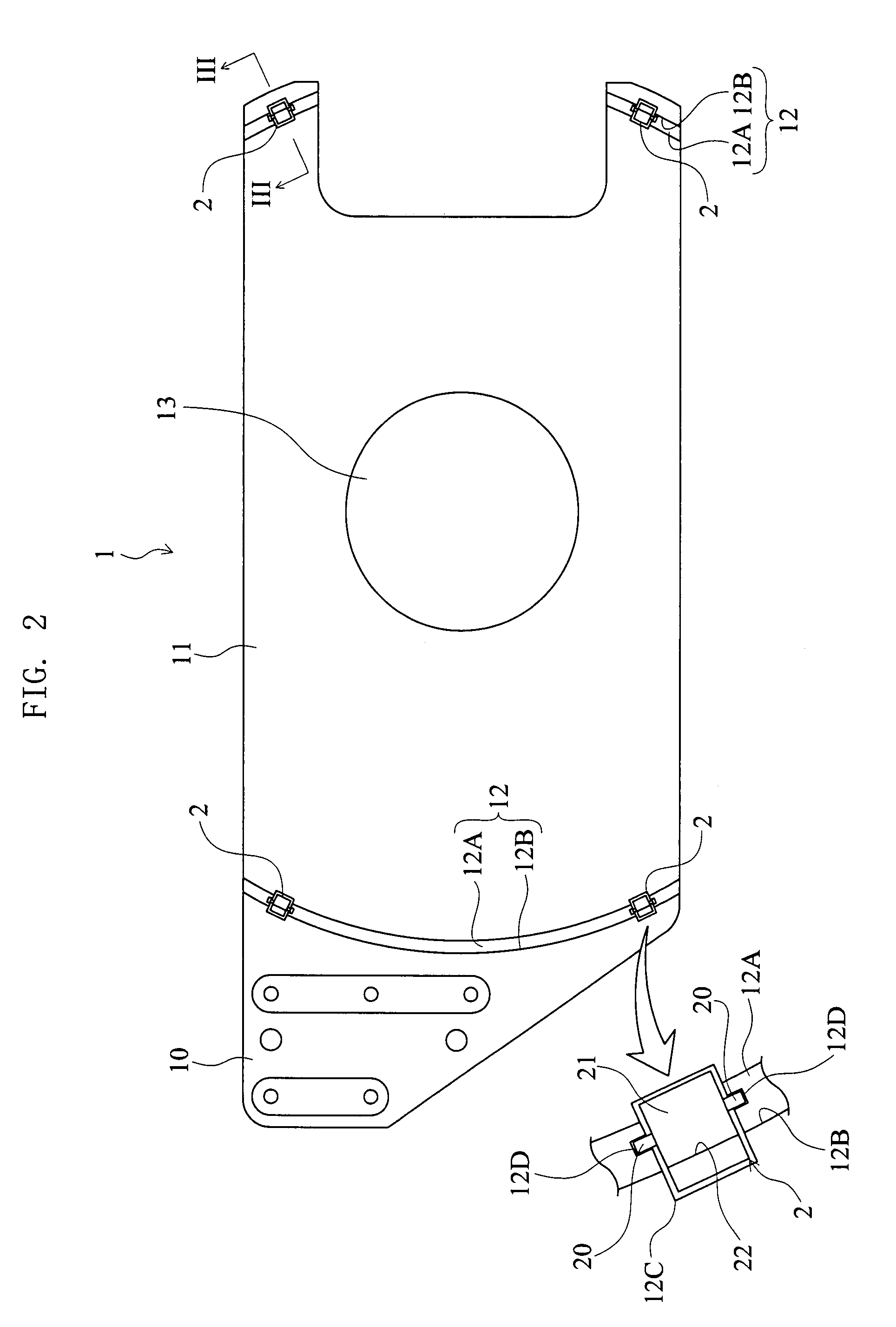
[0027]FIG. 1 through 3 show an embodiment of a work holding mechanism according to the present invention. The illustrated work holding mechanism A is a mechanism for horizontally holding a flat work such as a wafer W, and as shown in FIG. 1, includes a base member 1 and a plurality of guide members 2. The wafer W is formed with a cutout (orientation flat) in its perimeter, though this is not shown in FIG. 1. The wafer W has, for example, a diameter of 300±0.2 mm, a thickness of 775±25 μm and a weight of 125 g.

[0028]The base member 1 is formed of aluminum, ceramic or engineering plastic for example. The base member 1 has a base end 10 for attachment to an unillustrated arm tip of a material handling / transport equipment, and a wafer-supporting bed 11 for placement of the wafer W. For weight reduction, the width of the base end 10 over to the bed 11 is smaller than t...


PUM


Abstract

A work holding mechanism for horizontally holding a flat work is incorporated in work transport equipment. The holding mechanism includes a base member for supporting the work and a plurality of guide members provided at the base member. Each guide member includes a shaft, a contact portion and a limit portion. The shaft is pivotally supported by the base member. The contact portion comes into contact with part of the lower surface of the perimeter of the work and is pushed down, with the shaft as a fulcrum, when the work is placed on the base member. The limit portion is raised, with the shaft as a fulcrum, to face part of the side surface of the perimeter of the work when the contact portion is lowered.

Description

BACKGROUND OF THE INVENTION[0001]1. Field of the Invention[0002]The present invention relates to a work holding mechanism suitable for material handling / transporting equipment configured to transport a work such as a wafer while holding the work horizontally.[0003]2. Description of the Related Art[0004]A conventional work holding mechanism is disclosed in JP-A-2006-150538, for example. The work holding mechanism described in this document includes a pair of tip pawls provided at a tip of a base member (transport hand), and a pair of clamp pawls for pushing a wafer, which is placed on the base member, toward the tip of the base member. The clamp pawls are pivotable in predetermined directions by an actuating mechanism such as an air cylinder, coil springs, and so on. According to such a holding mechanism, the wafer on the base member can be pushed by the clamp pawls toward the tip of the base member, thereby positioning and holding the wafer on the base member, between the clamp pawl...

Claims


Application Information

Patent Timeline
Patent Type & Authority Patents(United States)
IPC IPC(8): B25J15/00B65G49/07
CPCH01L21/67259H01L21/68707Y10S294/907Y10S414/141H01L21/67742
Inventor KUSHIDA, TOSHIKAZUOKA, YOHEI
Owner DAIHEN CORP
Why Eureka
Try Eureka