Carbon nanotube collimator fabrication and application

Inactive Publication Date: 2010-07-06
RGT UNIV OF CALIFORNIA +1
View PDF25 Cites 21 Cited by
  • Summary
  • Abstract
  • Description
  • Claims
  • Application Information

AI Technical Summary

Benefits of technology

[0012]A forth objective of the invention is to provide new methods, systems, apparatus and devices for fabricating individual CNT collimators for applications

Problems solved by technology
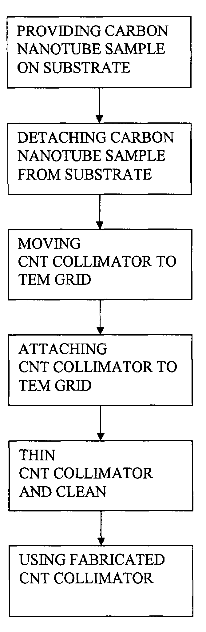
However, the nano size of the CNTs makes it difficult to precisely control the position and the orientation of the CMT.
As a result, the ex

Method used


Image

  • Carbon nanotube collimator fabrication and application
  • Carbon nanotube collimator fabrication and application
  • Carbon nanotube collimator fabrication and application

Examples


Embodiment Construction

[0038]Before explaining the disclosed embodiments of the present invention in detail it is to be understood that the invention is not limited in its application to the details of the particular arrangements shown since the invention is capable of other embodiments. Also, the terminology used herein is for the purpose of description and not of limitation.

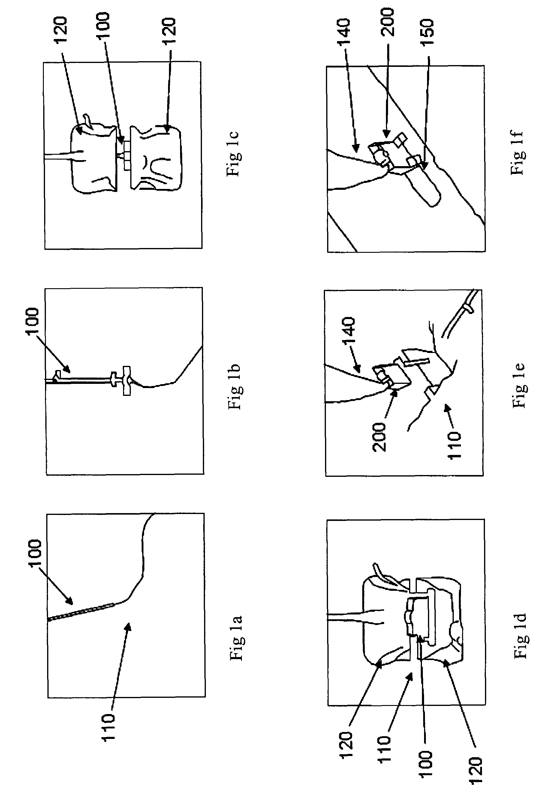
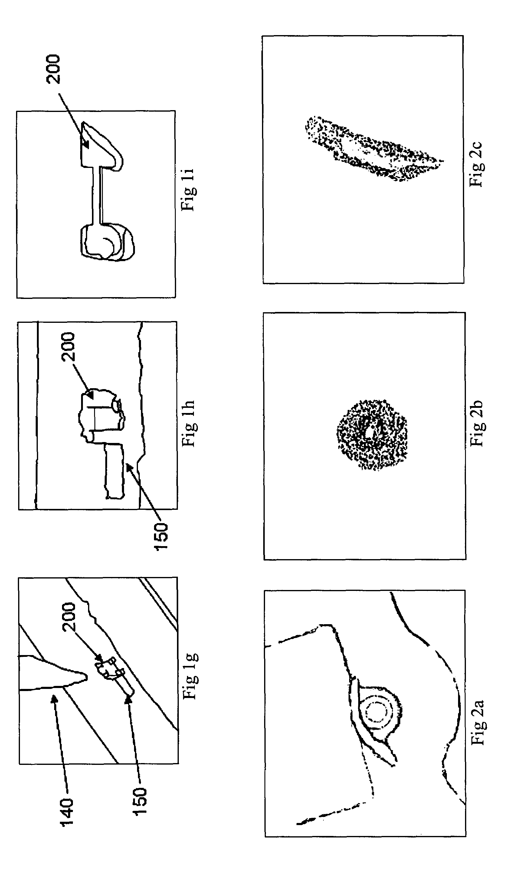
[0039]The following is a list of the reference numbers used in the drawings and the detailed specification to identify components:[0040]100 carbon nanotube[0041]110 substrate[0042]120 trench[0043]130 CNT side[0044]135 CNT bottom[0045]140 micromanipulator needle[0046]150 transmission electron microscopy grid[0047]200 CNT collimator sample

[0048]It would be useful to provide abbreviations used herein before discussing the fabrication and use of the carbon nanotube collimators of the present invention including:

CNT carbon nanotube

CVD chemical vapor disposition

F-CNT fiber coated carbon nanotube

FIB focused ion beam

TEM transmission electron...


PUM


Abstract

Apparatus, methods, systems and devices for fabricating individual CNT collimators. Micron size fiber coated CNT samples are synthesized with chemical vapor deposition method and then the individual CNT collimators are fabricated with focused ion beam technique. Unfocused electron beams are successfully propagated through the CNT collimators. The CNT nano-collimators are used for applications including single ion implantation and in high-energy physics, and allow rapid, reliable testing of the transmission of CNT arrays for transport of molecules.

Description

STATEMENT OF GOVERNMENTAL SUPPORT[0001]The invention described and claimed herein was made in part utilizing funds supplied by the U.S. Department of Energy under Contract No. DE-AC02-05CH11231. The Government has certain rights in this invention.FIELD OF THE INVENTION[0002]This invention relates to carbon nanotubes and, in particular, to methods, systems, apparatus and devices for fabricating carbon nanotube collimators for use for applications where a narrow, well-collimated beam of charged particles is required such as use for single ion implantation, as nano-aperture for single ion implementation for quantum computers, high-energy physics including e31-e+ collision or p−-p+ collision, and rapid, reliable testing of the transmission of CNT arrays for transport of molecules.BACKGROUND AND PRIOR ART[0003]The hollow structure is a remarkable feature of carbon nanotubes (CNTs) as described in Iijima S., Nature (London) 354, pp. 56-8 (1991) since it provides a significant chance to us...

Claims


Application Information

Patent Timeline
IPC IPC(8): H01J37/26G21K5/04
CPCG21K1/02G21K1/025Y10S977/842Y10S977/742Y10S977/84Y10S977/734Y10S977/849
Inventor CHOW, LEECHAI, GUANGYUSCHENKEL, THOMAS
Owner RGT UNIV OF CALIFORNIA
Why Eureka
Try Eureka