
Resolver and manufacturing method of the same

a technology of a solution and a manufacturing method, which is applied in the direction of applying solid insulation, instruments, windings, etc., can solve the problems of easy damage to the connection between the wire and the terminal pin, the damage of the wire by the shock and vibration of the vehicle, and the damage to the wire. , to achieve the effect of improving the reliability of the connection and minimizing the damage to the wires

Inactive Publication Date: 2010-07-13
NIDEC CORP
View PDF14 Cites 23 Cited by
  • Summary
  • Abstract
  • Description
  • Claims
  • Application Information

AI Technical Summary

Benefits of technology

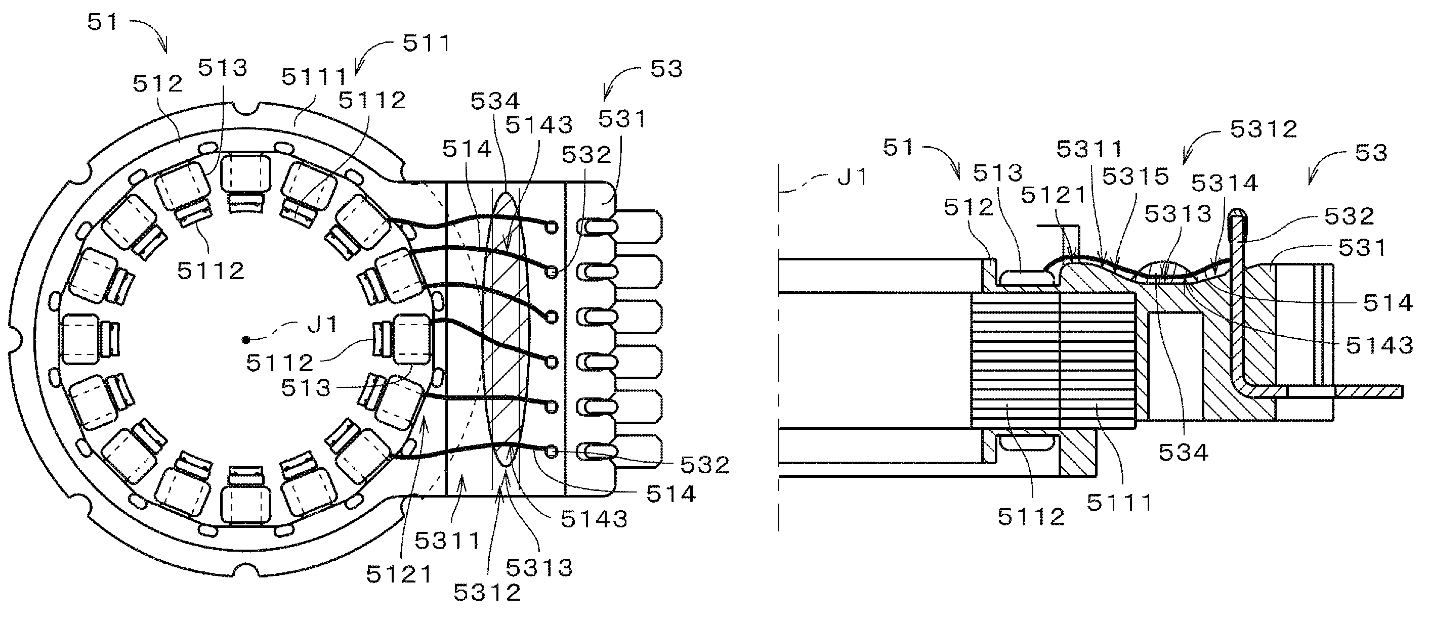
[0009]In order to overcome the problems described above, a preferred embodiment of the present invention provides a resolver which includes at a wiring surface arranged at a terminal block a groove portion at which a plurality of slackened portions of wires are accommodated. By virtue of such configuration, damage which may occur to the wires is minimized thereby improving reliability of the connection between.
[0010]Also, another preferred embodiment of the present invention provides a resolver having a plurality of wires, each having a first winding portion which is wound around a terminal pin from a substantially bottom end portion thereof toward the tip portion thereof, and a second winding portion which is wound around the terminal pin from the substantially tip portion thereof toward the bottom portion thereof partially overlapping with the first winding portion. The wires and the terminal pins are soldered or welded to one another so as to be connected. By virtue of such configuration, the possibility of the wire coming unwound from the terminal pin before the welding is carried out is minimized.
[0011]Also, a manufacturing method of the resolver according to another preferred embodiment of the present invention includes a step of forming a stator portion and a connector portion at which a wiring surface is arranged above the terminal block and includes a groove portion, a step of winding one end of a wire whose other end is wound around either one of the terminal pin and the tooth around either one of the corresponding terminal pin and the corresponding tooth detouring around a jig arranged at a shortest route connecting the either one of the terminal pin and the tooth and the either one of the corresponding terminal pin and the corresponding tooth, a step of forming a slackened portion at the wire by removing the jig from its original position, and a step accommodating the slackened portion at the groove portion of the connector portion. By such method, the reliability of the connection between the terminal pins and the coils is improved.

Problems solved by technology

The conventional method of connecting the wire to the terminal pin, however, has a problem in that the connection between the wire and the terminal pin may be damaged by shocks and vibrations applied thereto from the vehicle due to a small radius of the wire used to form the coils.
Further, when the wire which is wound around the terminal pin becomes unwound before the wire is welded to the terminal pin, the connection between the wire and the terminal pin is easily damaged due to the shocks and vibrations of the vehicle applied thereto.
Such deformation may cause the wire extending from the terminal pin to the coil to be erroneously connected to the terminal block causing the wire to be damaged by the shocks and vibrations of the vehicle.

Method used


Image

  • Resolver and manufacturing method of the same
  • Resolver and manufacturing method of the same
  • Resolver and manufacturing method of the same

Examples


Embodiment Construction

[0029]Note that in the description of preferred embodiments of the present invention herein, words such as upper, lower, left, right, upward, downward, top and bottom for describing positional relationships and directions merely indicate positional relationships and directions in the drawings. Such words do not indicate positional relationships and directions of the members mounted in an actual device. Also note that reference numerals, figure numbers and supplementary descriptions are shown below for assisting the reader in finding corresponding components in the description of the preferred embodiments below to facilitate the understanding of the present invention. It is understood that these expressions in no way restrict the scope of the present invention.

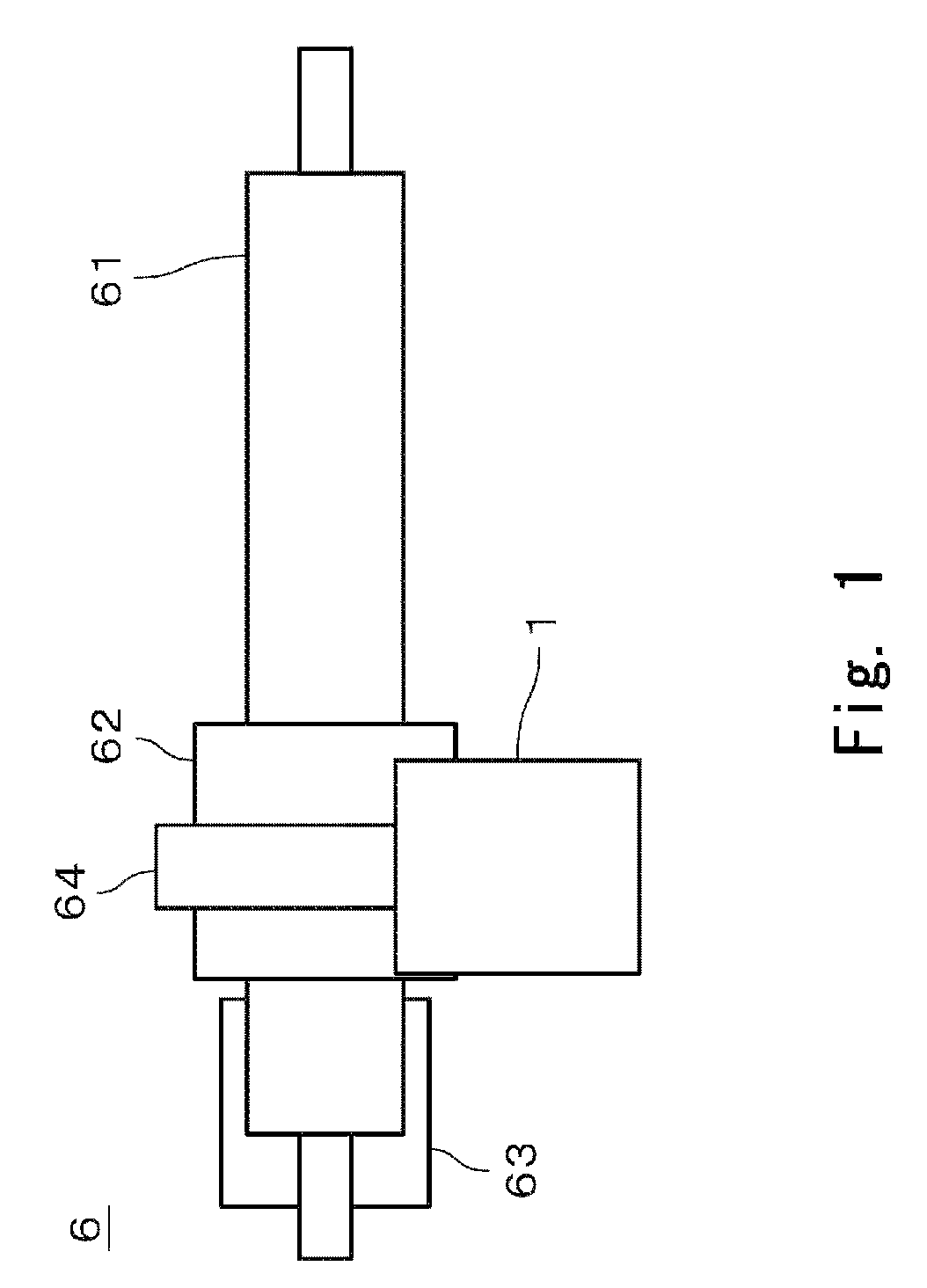
[0030]FIG. 1 is a schematic diagram of a power steering apparatus 6 having a resolver according to a first preferred embodiment of the present invention. The power steering apparatus 6 is preferably used in a vehicle such as a ...


PUM

PropertyMeasurementUnit
angleaaaaaaaaaa
angleaaaaaaaaaa
angleaaaaaaaaaa

Abstract

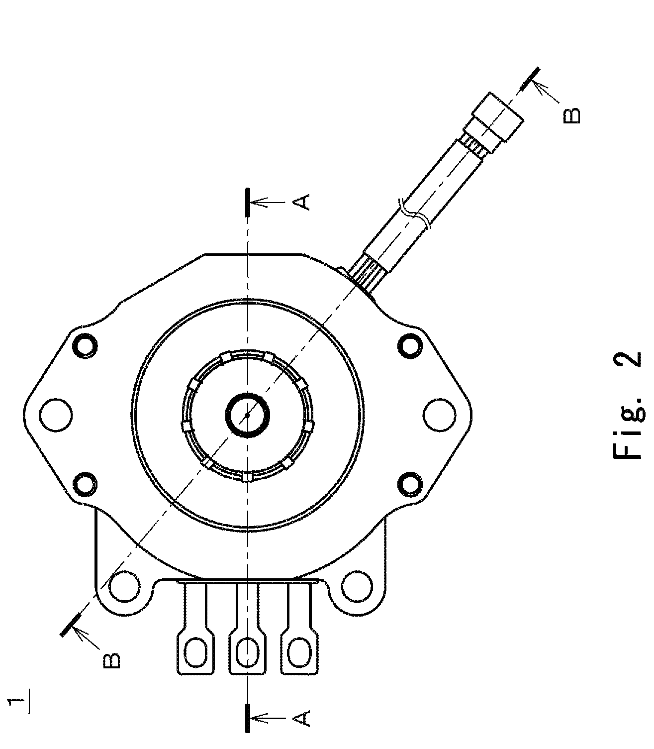
In a resolver of a motor, a plurality of wires forming a plurality of coils arranged at a resolver stator portion are arranged at a wiring surface which is arranged at a terminal block of a connector portion and extends between an annular shape surface arranged substantially perpendicularly to a central axis at a core back of an insulator and a plurality of terminal pins, and are connected to a control unit via the terminal pins. Each of the wires of the resolver includes a slackened portion formed at a portion thereof between corresponding terminal pins and corresponding coils. The slackened portion is accommodated in a groove portion arranged at the wiring surface of the connector portion in order to minimize the possibility of damaging the wire improving reliability of the connection between the terminal pin and the coil.

Description

BACKGROUND OF THE INVENTION[0001]1. Field of the Invention[0002]The present invention relates to a resolver which detects an angular position of an object, and a manufacturing method of the resolver.[0003]2. Description of the Related Art[0004]Conventionally, a hydraulic power steering apparatus is used in a vehicle such as a passenger car or the like to assist an operator in maneuvering the vehicle. The hydraulic power steering apparatus uses a pump operated by an engine of the vehicle to generate force to assist the operator's steering. In recent years, an electric power steering (EPS) which uses a motor operated by a vehicle battery has become available. The EPS is more power efficient than the conventional hydraulic power steering.[0005]In order to achieve highly accurate performance, the EPS requires an angle detection mechanism which is operable to accurately detect a rotary angle of the motor. Further, components used in the vehicle are required to function in various types o...

Claims


Application Information

Patent Timeline
Patent Type & Authority Patents(United States)
IPC IPC(8): H02K3/50H02K15/10
CPCG01D5/2013H02K3/522H02K5/225H02K11/0031Y10T29/53143Y10T29/49009Y10T29/4902Y10T29/53157H02K11/225
Inventor KATAOKA, NAKABANAKANISHI, KEITA
Owner NIDEC CORP
Learn More