
Frequency multiplier

a frequency multiplier and frequency technology, applied in the field of frequency multipliers, can solve the problems of reducing system performance, requiring a substantial input power for frequency multipliers, and reducing the efficiency of generating harmonics in known frequency multipliers

Active Publication Date: 2010-07-20
VEONEER US LLC
View PDF6 Cites 3 Cited by
  • Summary
  • Abstract
  • Description
  • Claims
  • Application Information

AI Technical Summary

Problems solved by technology

However, these known frequency multipliers require a substantial input power in order to drive the transistor hard enough to generate the desired harmonics.
Additionally, the efficiency of generating the harmonics in these known frequency multipliers is typically low and becomes worse as the frequency increases, thereby also degrading system performance.

Method used


Image

  • Frequency multiplier
  • Frequency multiplier
  • Frequency multiplier

Examples


Embodiment Construction

[0012]For simplicity and ease of explanation, the invention will be described herein in connection with various embodiments thereof. Those skilled in the art will recognize, however, that the features and advantages of the various embodiments may be implemented in a variety of configurations. It is to be understood, therefore, that the embodiments described herein are presented by way of illustration, not of limitation.

[0013]As used herein, an element or step recited in the singular and proceeded with the word “a” or “an” should be understood as not excluding plural said elements or steps, unless such exclusion is explicitly stated. Furthermore, references to “one embodiment” of the present invention are not intended to be interpreted as excluding the existence of additional embodiments that also incorporate the recited features. Moreover, unless explicitly stated to the contrary, embodiments “comprising” or “having” an element or a plurality of elements having a particular property...


PUM


Abstract

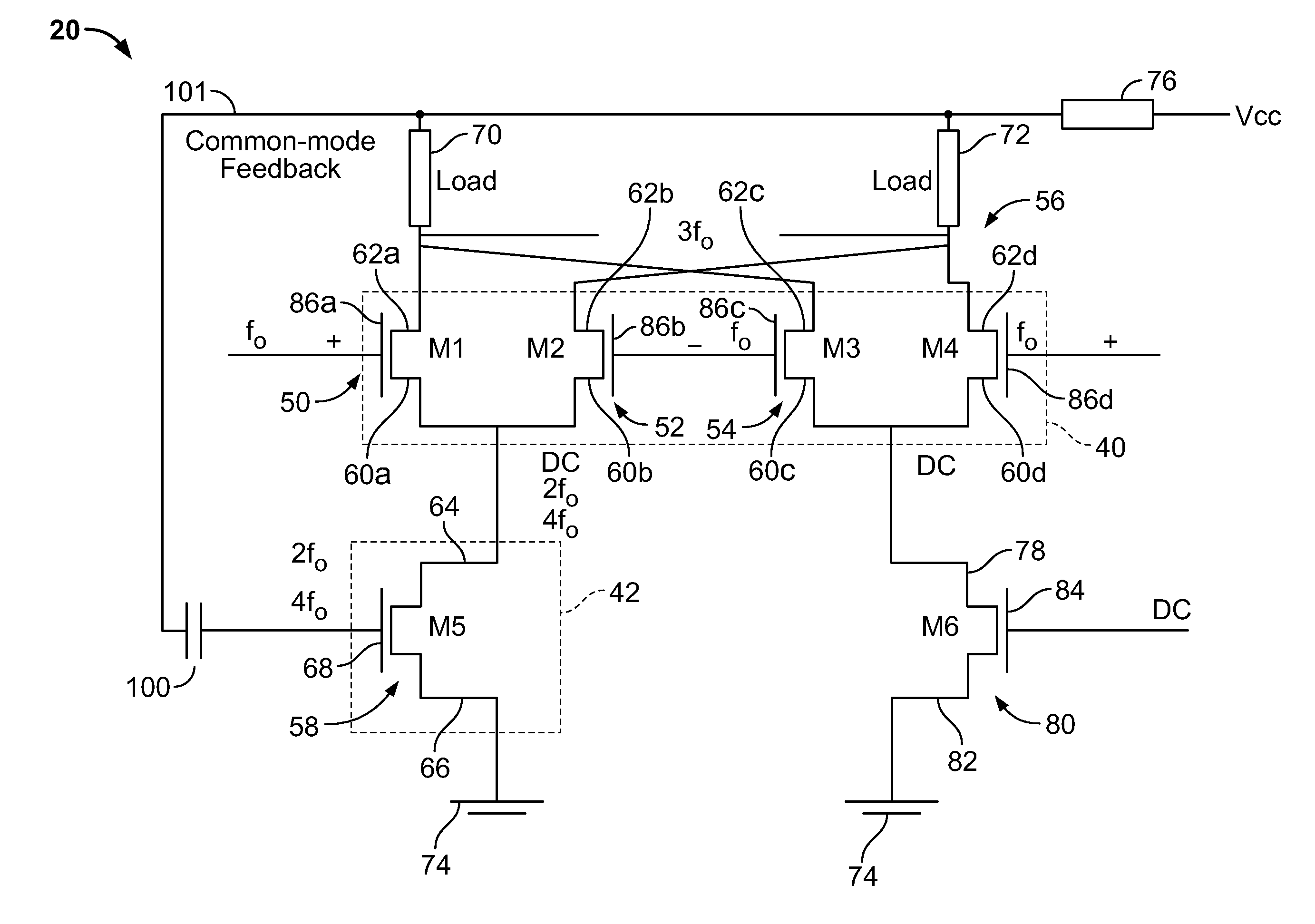
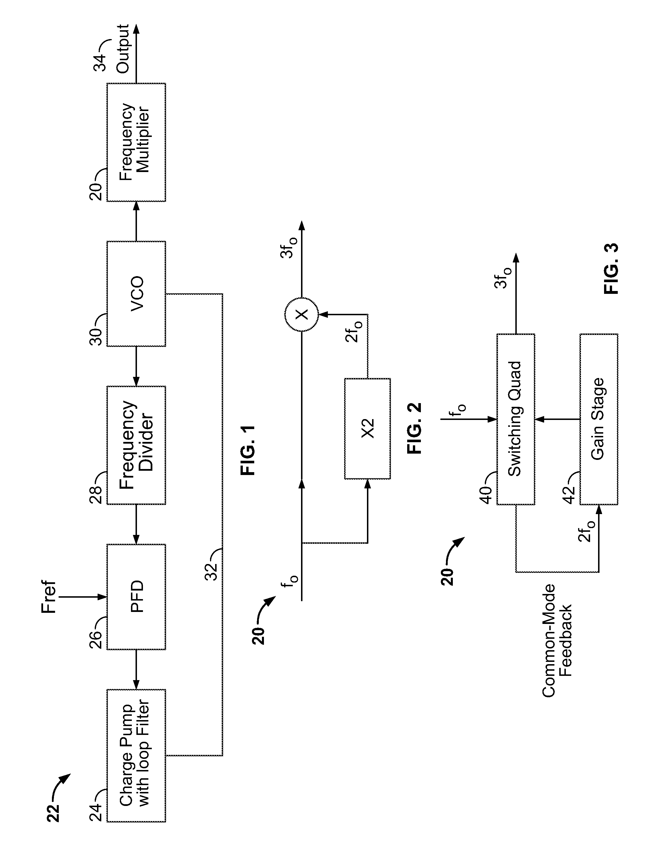
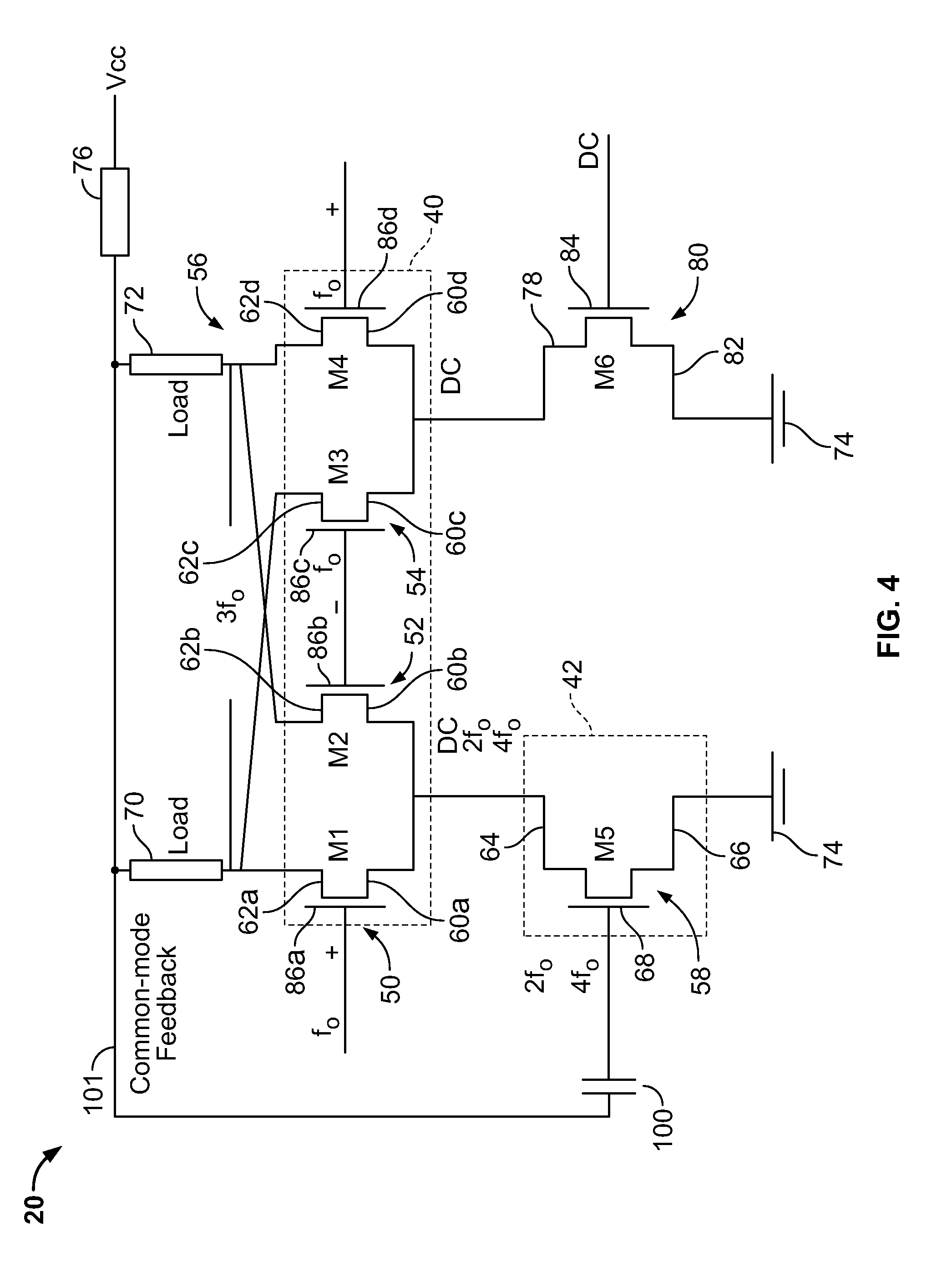
A frequency multiplier is provided that includes a switching component having a plurality of differential pairs of transistors. The frequency multiplier further includes a gain stage. A common mode feedback generated by the switching component is also provided to the gain stage.

Description

BACKGROUND OF THE INVENTION[0001]This invention relates generally to frequency multipliers, and more particularly, to a frequency multiplier having a common-mode feedback.[0002]Frequency multipliers are commonly used in radio applications (e.g., radio transmitter or receiver) and other radio frequency (RF) applications, such as radar applications (e.g., automotive radar) to multiply the base frequency of an oscillator by a predetermined factor (e.g., factor of 2 or 3). The multiplied frequency is driven in a final stage to produce a signal output, for example, to an antenna. Frequency multipliers allow the use of a stable frequency reference source (e.g., a crystal oscillator or on-chip voltage controlled oscillator (VCO)), to generate frequencies which may be difficult to produce directly from the VCO (e.g., 24 GHz operation). In digital applications, frequency multipliers are often used in phase-locked loops to generate a desired frequency from an external reference frequency.[000...

Claims


Application Information

Patent Timeline
Patent Type & Authority Patents(United States)
IPC IPC(8): H03B19/00
CPCH03B19/14H03D2200/0019
Inventor LU, YUMINGRESHAM, ROBERT IAN
Owner VEONEER US LLC
Learn More