System and method for low loss waveguide bends

a waveguide and low-loss technology, applied in the field of system and method for low-loss waveguide bends, can solve the problems of diffraction loss, low index waveguides are not suitable for use, waveguides experience more scattering loss, etc., and achieve the effect of facilitating proper alignment of masks

Inactive Publication Date: 2010-07-20
BROADCOM INT PTE LTD
View PDF38 Cites 1 Cited by
  • Summary
  • Abstract
  • Description
  • Claims
  • Application Information

AI Technical Summary

Benefits of technology

[0012]A low index contrast waveguide medium using total internal reflection (TIR) is used to create a relatively sharp (approximately 90°) bend for optical signals traversing the waveguide. A discontinuity of the medium (such as air) creates a turning mirror within the waveguide path. By curving the discontinuity, the entire input optical beam is focused into the output portion of the waveguide, thereby compensating for the diffraction loss at the turning mirror.
[0013]Reproducibly fabricating the waveguide bends with turning mirrors is accomplished by defining the TIR mirror on the same mask pattern with the waveguide pattern. To facilitate proper alignment of the masks certain portions of the waveguide on a first mask are extended and widened beyond their optimum physical size. This extended portion is then used to position an edge of a second mask for forming discontinuity in the medium, such that any misalignment introduced by manufacturing processes will not alter the relative position between the turning mirror and waveguide. The optical signal scattering loss caused by the extended portions of the waveguide are compensated for by adjusting the curvature.

Problems solved by technology

However, because of the tight optical confinement such high index contrast waveguides experience more scattering loss from roughness in the waveguide side-walls (introduced during manufacturing) than do low index contrast waveguides.
Thus, low index waveguides are not suitable for use in devices requiring sharp bends along the optical signal path.
The extra phase delay distorts the guided wave front and results in diffraction loss.
Even with submicron alignment accuracy tools, there is no guarantee that the shape and position of the turning mirror can be reproduced within a given accuracy range.
Slight misalignment will have large effects on the efficiency of the turning mirror to perform its intended function.

Method used


Image

  • System and method for low loss waveguide bends
  • System and method for low loss waveguide bends
  • System and method for low loss waveguide bends

Examples


Embodiment Construction

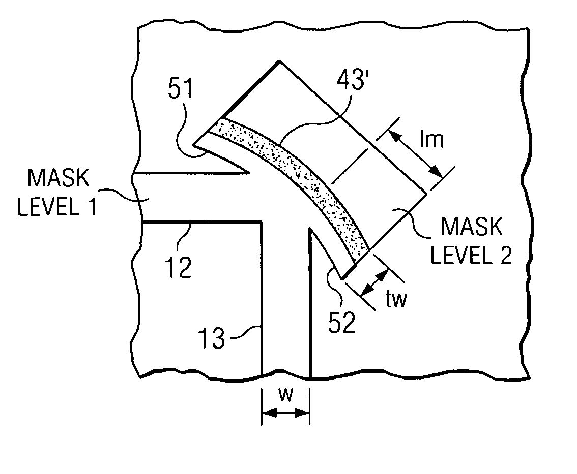
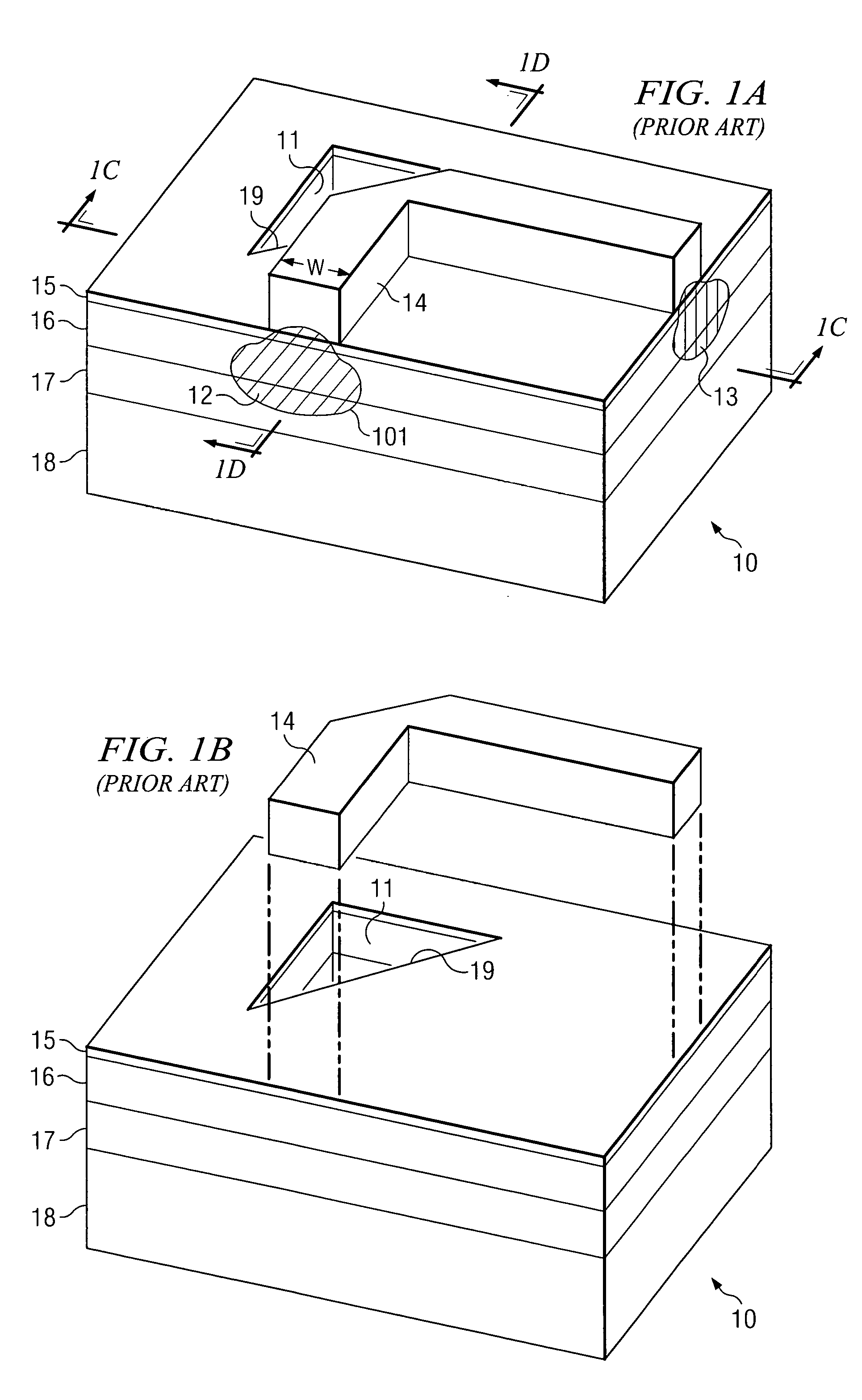
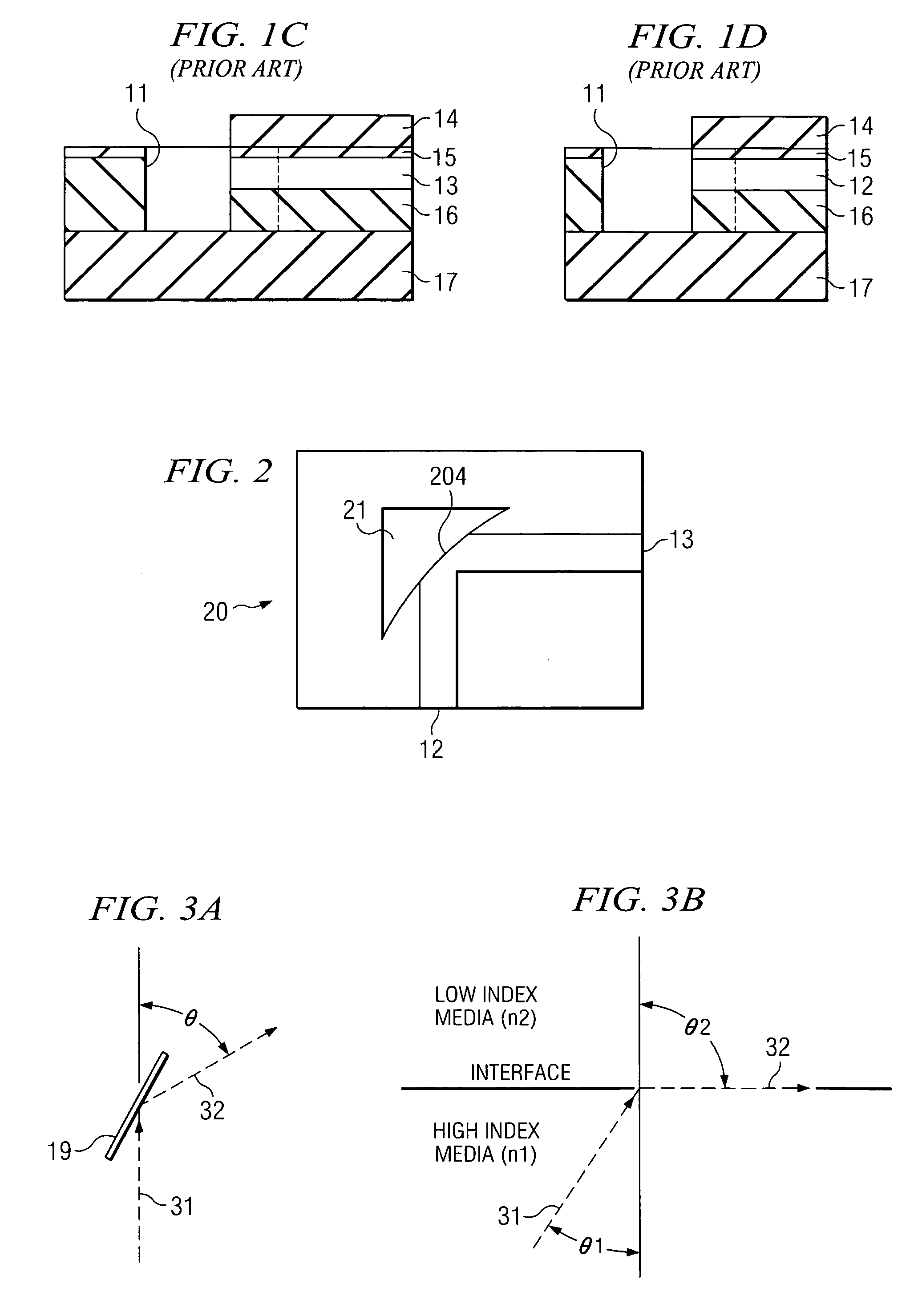
[0021]FIG. 2 shows one embodiment 20 in accordance with the invention illustrating curved front surface 204 of TIR discontinuity 21. Waveguide 20 can be a ridge waveguide as shown in FIG. 1A with a curved interface with discontinuity 21. The discontinuity is created by an air medium different from the medium of waveguide portion 12 as discussed with respect to FIG. 1A. The curved interface compensates for the phase difference of the reflected guided wave at different regions of the lateral mode profile thereby focusing at least a substantial portion (if not all) of the diffracted optical wave into output waveguide portion 13. The optimal radius of curvature depends on the configuration of the waveguide, such as the waveguide medium and the waveguide width. The optimal radius of curvature can be calculated with commercially available Finite Difference Time Domain (FDTD) code given waveguide parameters.

[0022]It is important to achieve very good alignment of optical surface 204 with wa...


PUM


Abstract

In one embodiment, there is disclosed a waveguide medium using total internal reflection to create a relatively sharp (approximately 90°) bend for optical signals traversing the waveguide. A discontinuity of the medium (such as air) is used to create a turning mirror within the waveguide path. By curving the discontinuity, the entire input optical signal is focused into the output portion of the waveguide, thereby compensating for the diffraction loss of the optical signal at the bend. In one embodiment in order to facilitate proper alignment of the masks certain portions of the waveguide on a first mask are extended (widened) beyond their optimum physical size. This extended portion is then used to position an edge of a second mask, such that optical signal scatter caused by the extended portions of the waveguide are compensated for by adjusting the curvature.

Description

STATEMENT REGARDING FEDERALLY SPONSORED RESEARCH OR DEVELOPMENT[0001]The invention was made in part with Government support by Defense Advanced Research Projects Agency (DARPA) under Grant Number MDA972-03-03-0004. The Government has certain rights in the invention.BACKGROUND OF THE INVENTION[0002]It has become common place to route optical signals within optoelectronic devices using waveguides created within a medium housing other circuit components. These devices are known as Photonic Integrated Circuits (PICs) and the passive waveguides are used to route optical signals between active devices on such circuits. Waveguides are also used in such circuits to route optical signals to / from other circuits, usually via fiber ports.[0003]As the density of such PICs increases, so does the need for sharp turns along the path of the waveguides. These sharp turns are often on the order of 90 degrees. To avoid radiation loss of the optical signal at the bends, waveguides with high index contra...

Claims


Application Information

Patent Timeline
Patent Type & Authority Patents(United States)
IPC IPC(8): G02B6/10
CPCG02B6/122G02B2006/12104G02B2006/12119G02B6/10G02B6/34
Inventor LIN, CHAO-KUNDJORDJEV, KOSTADINTAN, MICHAEL RENNE TY
Owner BROADCOM INT PTE LTD
Why Eureka
Try Eureka