
Structural member for a motor vehicle

a technology for structural components and motor vehicles, applied in the field of motor vehicles, can solve the problems of reducing the anticipated weight saving, reducing the design, and reducing the efficiency of the production process, and reducing the stress concentration effect of the core on the casing

Active Publication Date: 2010-07-27
FORD GLOBAL TECH LLC +1
View PDF9 Cites 7 Cited by
  • Summary
  • Abstract
  • Description
  • Claims
  • Application Information

AI Technical Summary

Benefits of technology

This solution provides a lightweight, high-strength structural member that can be easily integrated into motor vehicle bodyshells, offering improved resistance to bending and reduced weight compared to traditional designs, while maintaining efficient manufacturing processes.

Problems solved by technology

This can result in the design being bulky, heavy and expensive compared to a design using high strength steel, thereby eliminating much of the anticipated weight saving from the use of aluminum.
However, many existing methods of joining steel and aluminum such as brazing, adhesive bonding, bolting, or riveting have disadvantages in motor vehicle production, particularly for mass-produced passenger cars.
In particular, brazing provides inadequate joint strength.
Bolting is time consuming and difficult to accommodate where space on a component is limited, e.g., in the posts, or pillars of the upper structure of a bodyshell.
Blind riveting is more space efficient than bolting but can be even more time consuming.
However, such steels do not have a sufficiently high yield strength to produce the required combination of low weight and resistance to bending.
When steel having a sufficiently high yield strength (e.g. 950 MPa) is used, then self-piercing rivets cannot be used because the steel is too hard to yield during the riveting process.

Method used


Image

  • Structural member for a motor vehicle
  • Structural member for a motor vehicle
  • Structural member for a motor vehicle

Examples


Embodiment Construction

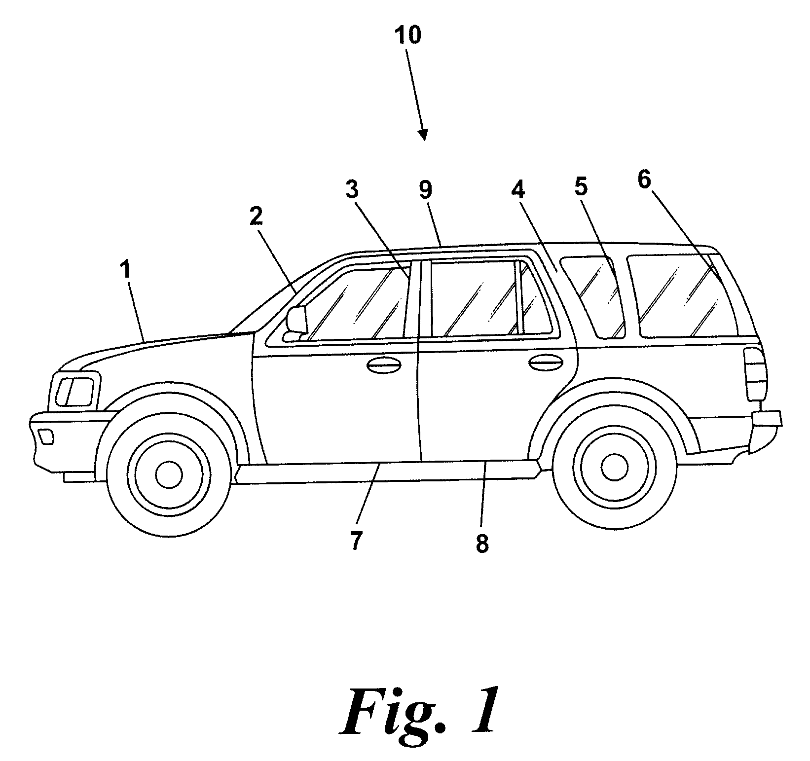
[0026]With reference to FIG. 1 there is shown a motor vehicle 10 having a body structure 1 comprised of a number of aluminum panels fastened to a number of underlying aluminum structural members (not visible on FIG. 1) and aluminum side structural members including an “A” post 2, a “B” post 3, a “C” post 4, a “D” post 5 and a “E” post 6, the side structural members being used to connect a roof 9 to a lower body structure. The vehicle 10 also includes a number of doors including a front door 7 and a rear door 8.

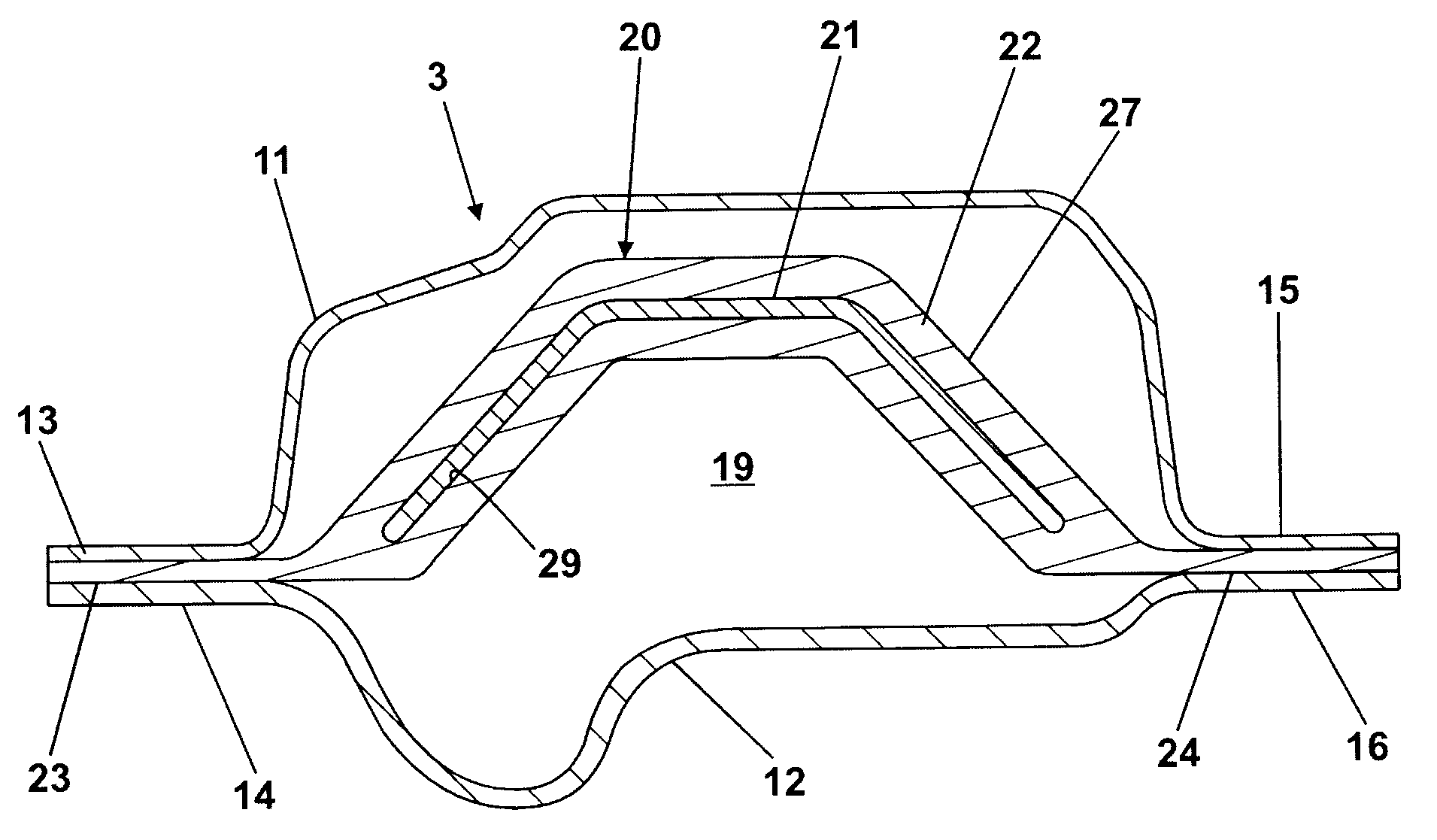
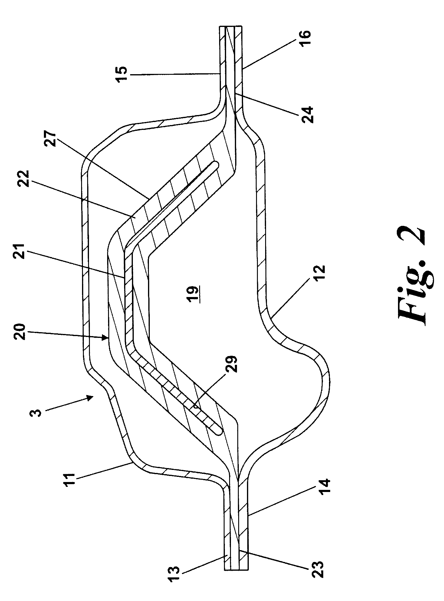
[0027]Referring further to FIG. 2, the “B” post 3 is formed from a first elongate panel member in the form of an aluminum pressing or stamping 11 and a second elongate panel member in the form of another aluminum pressing or stamping 12. The first pressing 11 has a first flange 13 extending along one edge and a second flange 15 extending along an opposite edge. Similarly the second pressing 12 has a first flange 14 extending along one edge and a second flange 16 extending alon...


PUM

PropertyMeasurementUnit
yield strengthaaaaaaaaaa

Abstract

A structural member of a motor vehicle, e.g., a “B” pillar, comprises a reinforcing member having an elongate core of ultra high strength steel and a casing of aluminum alloy, the casing having a constant section profile with a closed section cavity. The core is encased within the casing and the core and the casing bonded together by co-drawing the core and the casing through a die. The casing has a pair of spaced flanges which connect the reinforcing member to aluminum alloy pressings to form the structural member. The reinforcing member has considerable yield strength from the use of the ultra high strength steel in the core while the flanges, being of aluminum alloy, are readily joined by self-piercing rivets.

Description

FIELD OF THE INVENTION[0001]This invention relates to motor vehicles and in particular to the production of a motor vehicle having low weight and a high resistance to deformation in the event of a collision.BACKGROUND OF THE INVENTION[0002]It is well known that in order to improve fuel efficiency and emissions it is desirable to produce a lightweight motor vehicle. In order to achieve this goal, several vehicle manufacturers have proposed vehicles in which a substantial proportion of the body structure or bodyshell is constructed from a lightweight material such as an aluminum alloy. An example of such a vehicle construction is shown in U.S. Pat. No. 6,099,071.[0003]Some sections of such a bodyshell act as beams for which a substantial yield strength is a principal requirement. For a bodyshell assembled from aluminum pressings and extrusions, the yield strength of the aluminum dictates the thickness of material required in these places. This can result in the design being bulky, hea...

Claims


Application Information

Patent Timeline
Patent Type & Authority Patents(United States)
IPC IPC(8): B62D25/04
CPCB62D25/04B62D29/008Y10T29/49622
Inventor LAKIC, ALEX JOHN
Owner FORD GLOBAL TECH LLC
Learn More