Optimized internal manifold heat shield attachment

a heat shield and internal manifold technology, applied in the direction of turbine/propulsion fuel flow conduits, engine fuctions, jet propulsion plants, etc., can solve problems such as problems such as the attachment poin

Active Publication Date: 2010-08-03
PRATT & WHITNEY CANADA CORP
View PDF44 Cites 10 Cited by
  • Summary
  • Abstract
  • Description
  • Claims
  • Application Information

AI Technical Summary

Benefits of technology

[0005]In one aspect, the present invention provides a fuel manifold assembly for a gas turbine engine comprising an annular fuel manifold having at least one fuel conveying passage and defining at least one slow fuel flowing location, a heat shield at least partly enclosing the fuel manifold, a plurality of intermittent joints attaching the heat shield to the fuel manifold, the joints being circumferentially distributed about the fuel manifold and located as far away as possible from the slow fuel flowing location in the fuel manifold while maintaining the fuel manifold assembly dynamically balanced.
[0007]In a third aspect, the present invention provides a method of minimizing heat transfer from a heat shield to an internal fuel manifold of a fuel injection system in a gas turbine, the method comprising the steps of: determining at least one slow fuel flowing location in a fuel conveying passage of the fuel manifold; selecting joint locations as far away as possible away from the slow fuel flowing location; ensuring that the fuel injection system is dynamically balanced with said selected joint locations; and joining the heat shield to the fuel manifold at said selected joint locations.

Problems solved by technology

The attachment points are problematic as they act as heat input points transferring heat from the heat shield to the internal manifold.

Method used


Image

  • Optimized internal manifold heat shield attachment
  • Optimized internal manifold heat shield attachment
  • Optimized internal manifold heat shield attachment

Examples


Embodiment Construction

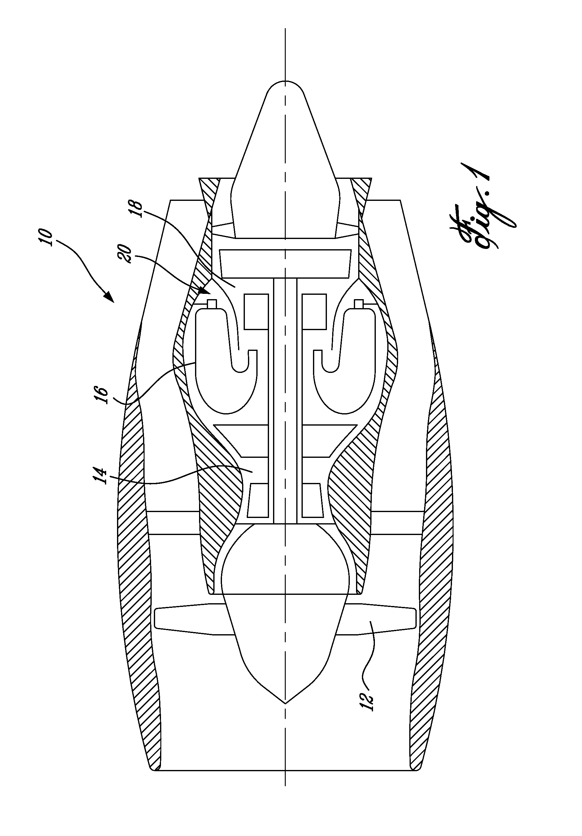
[0013]FIG. 1 illustrates a gas turbine engine 10 generally comprising, in serial flow communication, a fan 12 through which ambient air is propelled, a multistage compressor section 14 for pressurizing the air, a combustion section 16 in which the compressed air is mixed with fuel atomized, the mixture being subsequently ignited for generating hot combustion gases before passing through a turbine section 18 for extracting energy from the combustion gases.

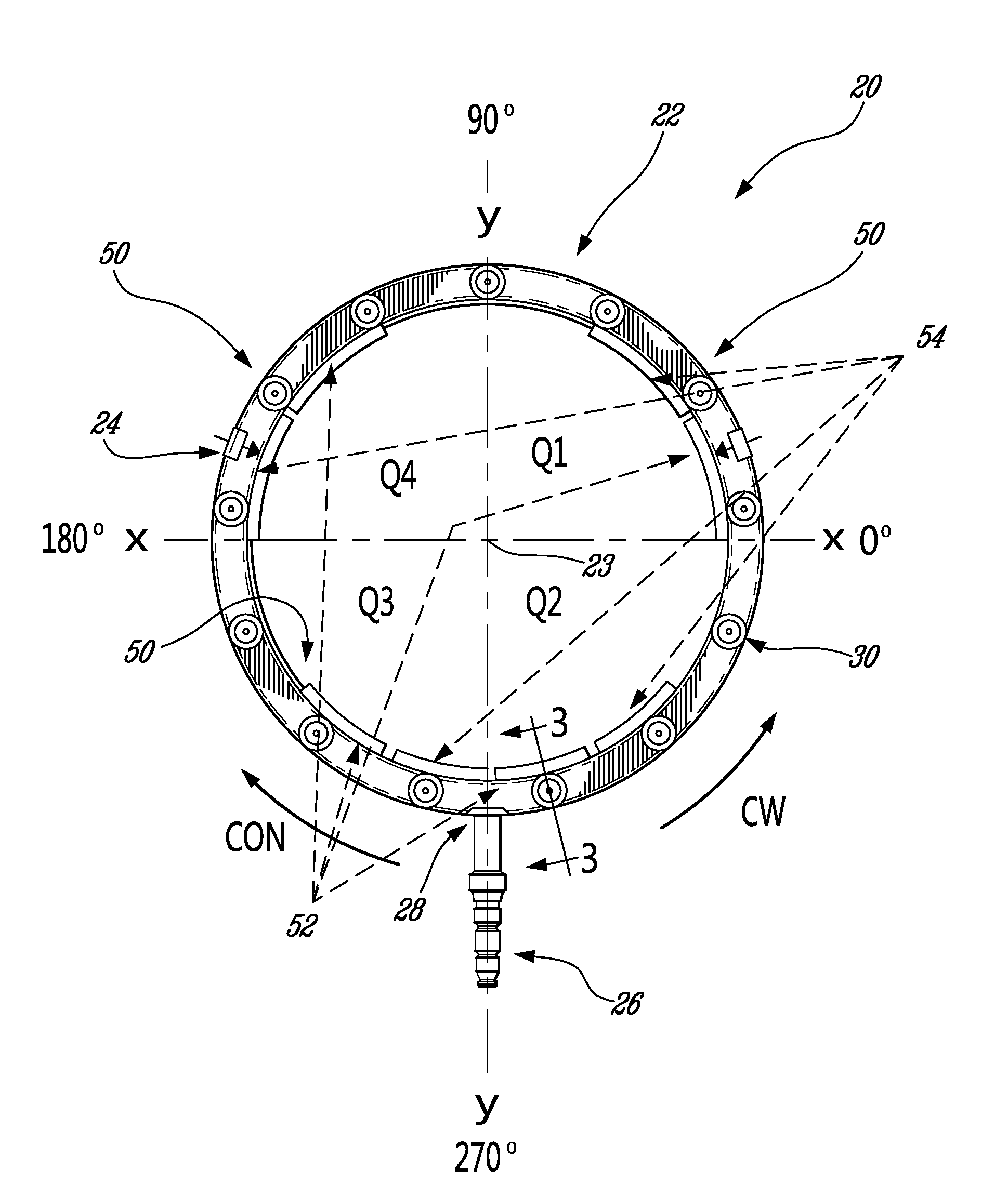
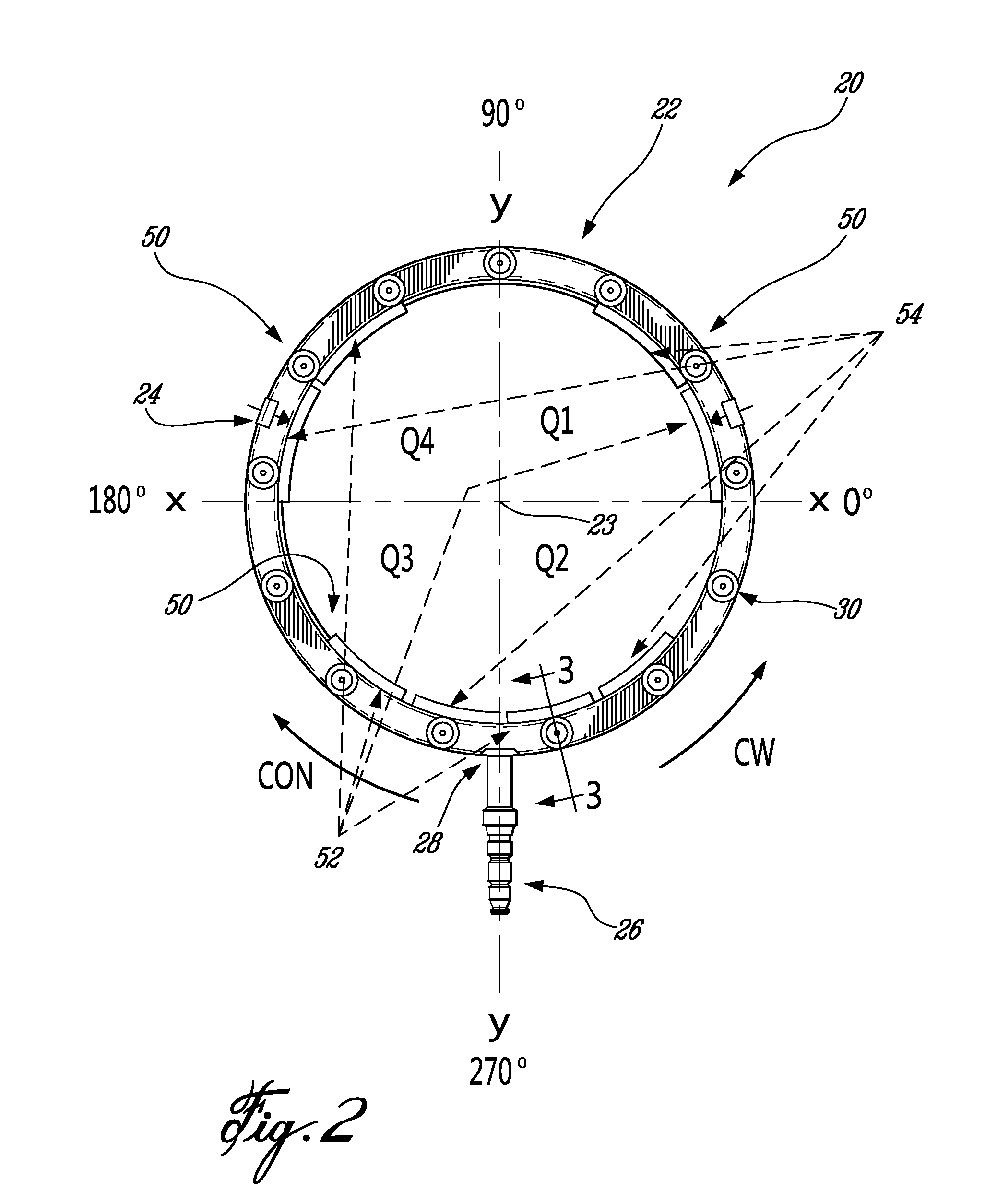
[0014]Fuel is injected into the combustor 16 of the gas turbine engine 10 by a fuel injection system 20 which is connected in fluid flow communication with a fuel source (not shown) and is operable to inject fuel into the combustor 16 for mixing with the compressed air from the compressor 14 and ignition of the resultant mixture.

[0015]Referring to FIGS. 2 and 3, the fuel injection system 20 comprises at least one fuel conveying member through which fuel flows. In the exemplary embodiment, the fuel injection system 20 includes an ann...


PUM


Abstract

A fuel manifold assembly for a gas turbine engine includes an annular fuel manifold having at least one fuel conveying passage and defining at least one slow fuel flowing location. A heat shield at least partly encloses the fuel manifold and a plurality of intermittent joints attach the heat shield to the fuel manifold. The joints are circumferentially distributed about the fuel manifold as far away from the slow flowing location as possible while maintaining the fuel manifold dynamically balanced.

Description

TECHNICAL FIELD[0001]The invention relates generally to a gas turbine engine and, more particularly to gas turbine engine fuel manifolds and methods of manufacturing same.BACKGROUND OF THE ART[0002]A fuel carrying member such as an internal manifold of a gas turbine engine must survive inside a hot environment while protecting the fuel flowing therein from being subjected to high temperatures. To accomplish this, a heat shield is used around the internal manifold to minimize convective heat transfer thereto. Typically, the heat shield is attached to the internal manifold by attachment points created by welding or brazing techniques. The attachment points are problematic as they act as heat input points transferring heat from the heat shield to the internal manifold. The heat shield is exposed to much higher temperatures than the internal manifold. Heat transfer occurs through the attachment points thereby causing a temperature increase in the fuel flowing in the internal manifold. T...

Claims


Application Information

Patent Timeline
Patent Type & Authority Patents(United States)
IPC IPC(8): F02C1/00F02G3/00
CPCF02C7/222F02C7/24F05D2260/20F05D2260/231
Inventor FISH, JASONPATEL, BHAWAN B.
Owner PRATT & WHITNEY CANADA CORP
Why Eureka
Try Eureka