Methods and apparatus for reducing stress in turbine buckets

a technology of turbine buckets and bucket metal, which is applied in the direction of machines/engines, liquid fuel engines, transportation and packaging, etc., can solve the problems of excessive stress in the bucket, premature failure, lack of adhesive bonds, etc., and achieve the effect of reducing stress

Inactive Publication Date: 2010-08-03
GENERAL ELECTRIC CO
View PDF11 Cites 19 Cited by
  • Summary
  • Abstract
  • Description
  • Claims
  • Application Information

AI Technical Summary

Benefits of technology

[0006]In one aspect, a method for reducing stress in a turbine bucket comprising a metallic base metal is provided. The method comprises providing a turbine bucket including at least one pocket formed therein, and filling at least one pocket defined in the bucket with a polymer composite having continuous fibers oriented in a resin matrix, such that the fibers have an orientation determined in accordance with a pre-selected frequency tuning of the bucket.
[0008]In a further aspect, a turbine bucket including a plurality of window pockets extending through an airfoil wall of the bucket is provided. The plurality of window pockets are positioned to facilitate reducing stress concentrations induced to the bucket. A composite comprising a resin matrix and layers of a fabric material is inserted within the window pocket.
[0009]It will be appreciated that configurations of the present invention provide reduced stress reducing stress in turbine buckets.

Problems solved by technology

During operation, turbine buckets are exposed to centrifugal loads, which may induce vibratory stresses in the bucket, cause fatigue in the bucket and / or premature failure.
However, such designs often lack sufficient adhesive bonds between the metal of the turbine bucket and the composite material.
Specifically, composites capable of withstanding the engine's high temperatures generally adhere poorly to the bucket metal because the composite material weighs more than the polymer filler material.
Configurations are disclosed that are applicable to fan blades, and more specifically to “propulsion engines.” As such, the sizes and shapes of the pockets are significantly limited.
Furthermore, U.S. Pat. No. 6,042,338, entitled “Detuned Fan Blade Apparatus and Method,” describes a “propulsion engine fan” and various types of blades with different pocket locations, but does not disclose blades of essentially one pocket with different rib structures.

Method used


Image

  • Methods and apparatus for reducing stress in turbine buckets
  • Methods and apparatus for reducing stress in turbine buckets
  • Methods and apparatus for reducing stress in turbine buckets

Examples


Embodiment Construction

[0020]As used herein, an element or step recited in the singular and proceeded with the word “a,”“an,” or “one” (and especially, “at least one”) should be understood as not excluding plural said elements or steps, unless such exclusion is explicitly stated. Furthermore, references to “one embodiment” (or to “other embodiments”) of the present invention are not intended to be interpreted as excluding either the existence of additional embodiments that also incorporate the recited features or of excluding other features described in conjunction with the present invention. Moreover, unless explicitly stated to the contrary, embodiments “comprising” or “having” an element or a plurality of elements having a particular property may include additional such elements not having that property.

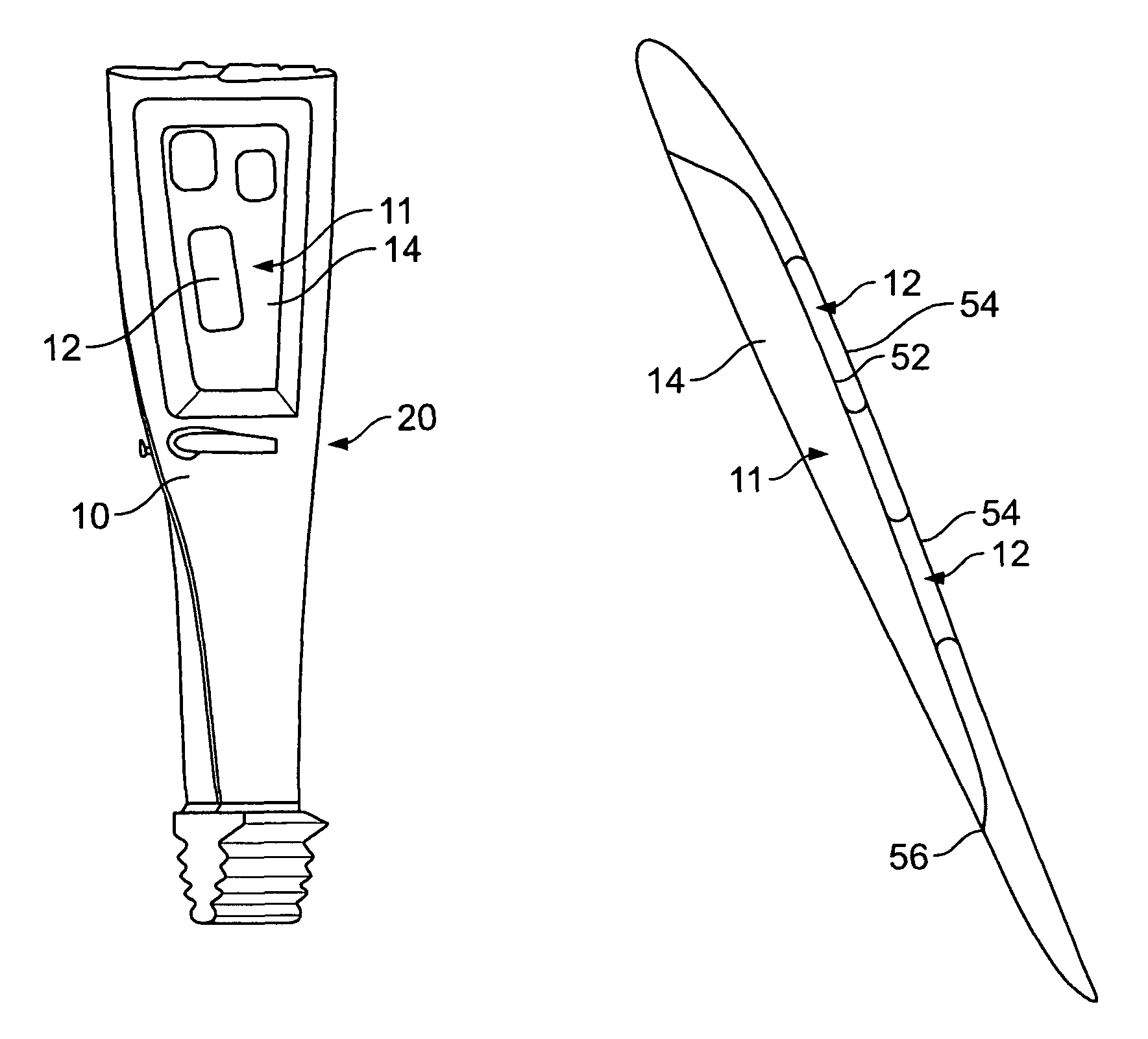
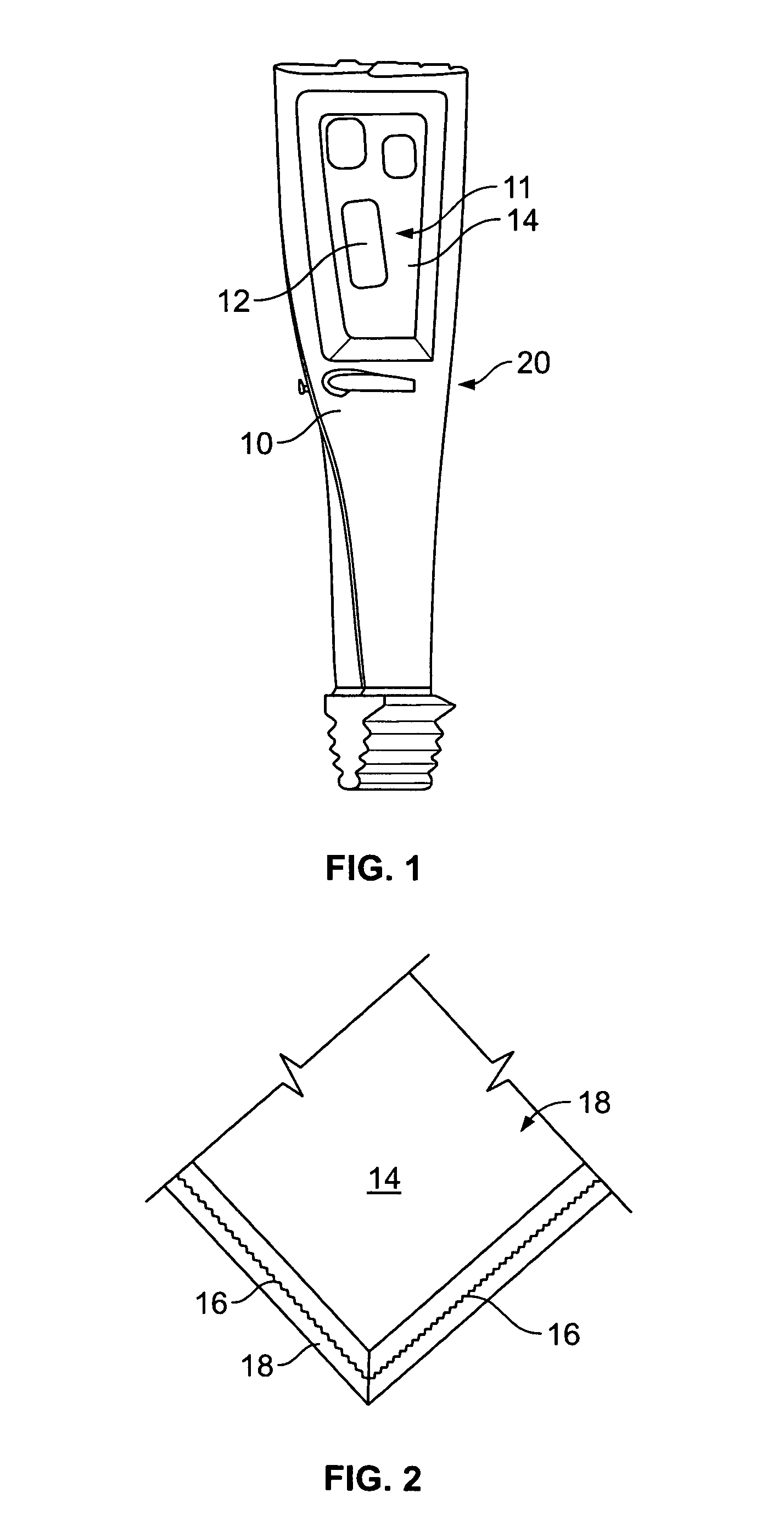
[0021]FIG. 1 is a schematic illustration of an exemplary opposed-flow, low-pressure (LP) steam turbine 10. Turbine 10 includes first and second low pressure sections 12 and 14. As is known in the art, e...


PUM

PropertyMeasurementUnit
stressaaaaaaaaaa
frequencyaaaaaaaaaa
strengthaaaaaaaaaa

Abstract

A method facilitates reducing stress in a turbine bucket including a metallic base metal. The method comprises providing a turbine bucket including at least one pocket formed therein, and filling at least one pocket defined in the bucket with a polymer composite having continuous fibers oriented in a resin matrix, such that the fibers have an orientation determined in accordance with a pre-selected frequency tuning of the bucket.

Description

BACKGROUND OF THE INVENTION[0001]This invention relates generally to steam turbines, and more particularly to methods and apparatus for reducing stress in turbine buckets.[0002]During operation, turbine buckets are exposed to centrifugal loads, which may induce vibratory stresses in the bucket, cause fatigue in the bucket and / or premature failure. Centrifugal loading may be a function of bucket operating speed, a weight of the bucket, and / or a location of the bucket relative to an engine centerline. As such, one known method of increasing the turbine bucket lifespan includes reducing the weight of the bucket. Additionally, the use of a hybrid bucket design allows for longer last stage buckets that equates to steam turbine output as the area increases. Also, the hybrid construction allows for more aerodynamic (wider chord) airfoils that improve stage efficiency. Lastly, the hybrid construction creates damping in the bucket / stage thereby improving the frequency response of the stage t...

Claims


Application Information

Patent Timeline
Patent Type & Authority Patents(United States)
IPC IPC(8): F01D5/14
CPCF01D5/16F01D5/26F01D5/282Y02T50/672Y02T50/673F05D2300/603Y02T50/60
Inventor BURDGICK, STEVEN S.LANAUD, CHRISTOPHEMAKINDE, ADEGBOYEGALIN, WENDYPRAVEEN, GRAMABANSAL, AMITABH
Owner GENERAL ELECTRIC CO
Why Eureka
Try Eureka