Method and apparatus for passively controlling airflow

a passive control and airflow technology, applied in the direction of pressure relieving devices on sealing faces, ventilation systems, heating types, etc., can solve the problems of reducing affecting the efficiency of the airflow control system, etc., to achieve the effect of reducing or eliminating, reducing the necessary central fan horsepower requirements, and being easy to moun

Active Publication Date: 2010-08-03
AMERICAN ALDES VENTILATION CORP
View PDF82 Cites 25 Cited by
  • Summary
  • Abstract
  • Description
  • Claims
  • Application Information

AI Technical Summary

Benefits of technology

[0016]Still another object of another embodiment of the invention is to provide a minimum flow control device that will continue to operate if a primary flow control device cannot be actuated to permit increasing airflow or it loses power.
[0017]Still another object of another embodiment of the invention is to provide a ventilation control assembly and system that can be easily maintained and / or removed from a terminal housing without disconnecting the terminal to which the assembly is attached from any duct or ventilation shaft.
[0020]Yet another object of another embodiment of the invention is to provide a device that reduces or eliminates the need for routine maintenance of the type that is required by mechanical or electrical systems of the past.
[0021]Still another object of another embodiment of the invention is to provide a device that can be easily mounted in a fire or non-fire rated ceiling or wall assembly.
[0022]Yet another object of another embodiment of the invention is to provide a device that will reduce the necessary central fan horsepower requirements and will facilitate saving on energy consumption by reducing the overall fan or ventilator requirements in the system.

Problems solved by technology

Whether the fan operates intermittently or continuously, this results in excessive energy consumption as a result of removing heated and conditioned air from spaces that may not require ventilation simply because the demand for ventilation exists in one or more of the areas.
Previous attempts to limit a central fan or ventilation system to ventilating only occupied areas by opening and closing terminal devices, caused fluctuations in duct air pressure, and ultimately caused a shift in the amount of air removed or delivered to one or more of the areas or zones.
This resulted in excessive ventilation rates and excessive energy usage in some areas and under-ventilating other areas, which in turn, caused poor indoor air quality related problems and a failure to meet minimum building code requirements in some instances.
Controlling the central fan speed or revolution per minute (RPM) to prevent the over or under-ventilation problem in zoned systems has been difficult, expensive and generally ineffective in the past.
However, a problem remained in that controlling the total system airflow does not ensure proper and / or constant airflow amounts at each zone branched duct.
If the VAV control device loses power, it will also lose it ability to control airflow.

Method used


Image

  • Method and apparatus for passively controlling airflow
  • Method and apparatus for passively controlling airflow
  • Method and apparatus for passively controlling airflow

Examples


Embodiment Construction

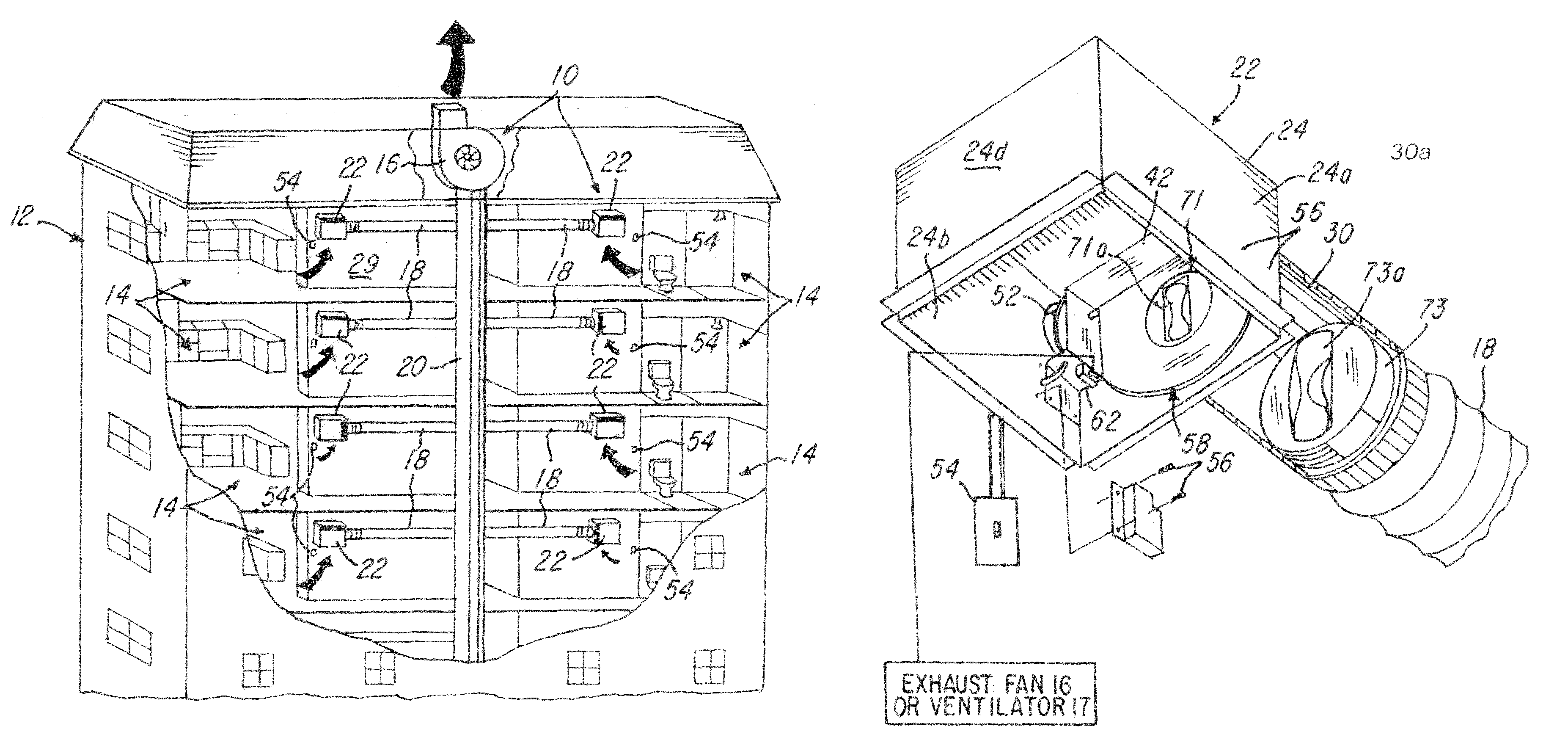
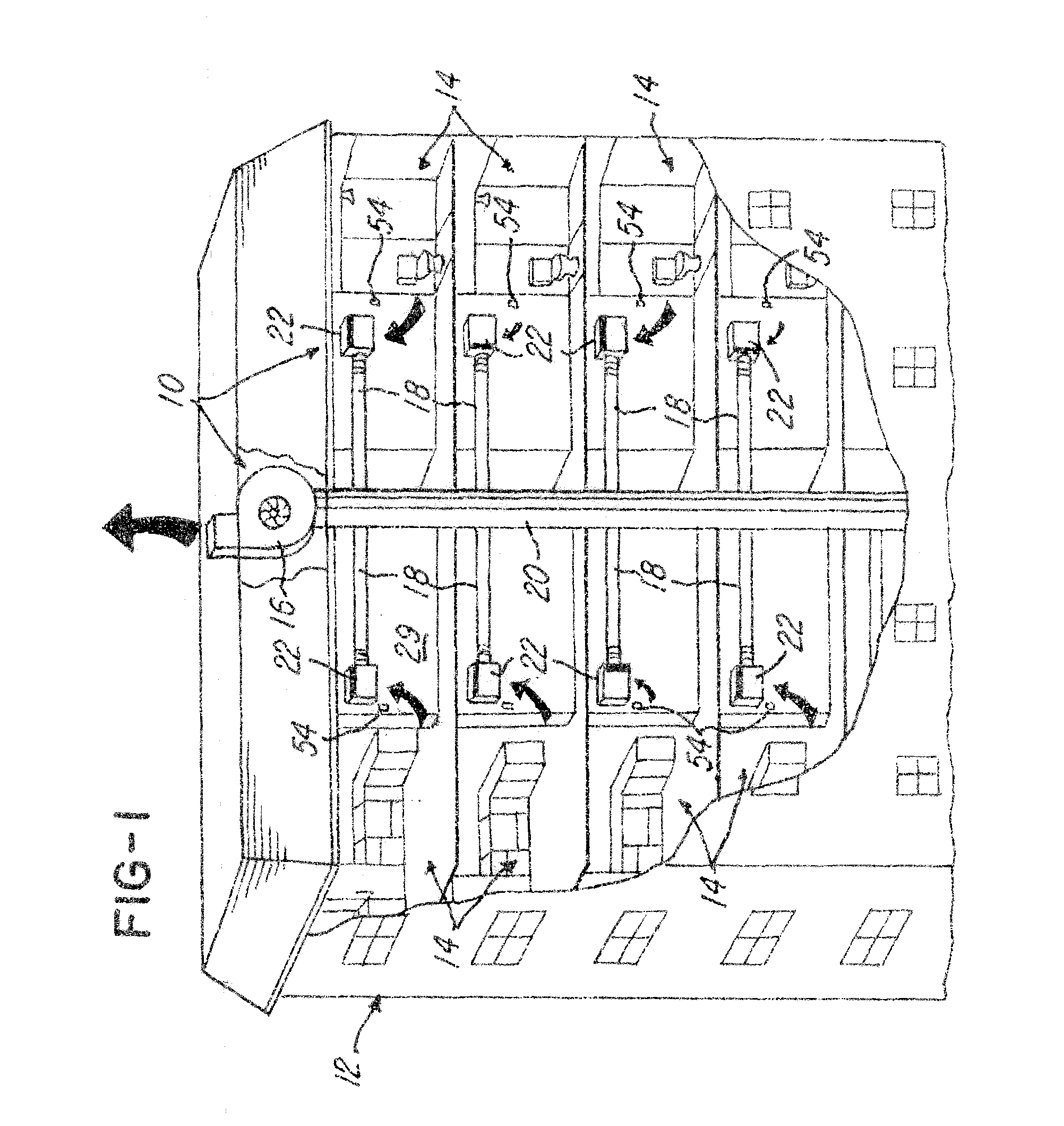
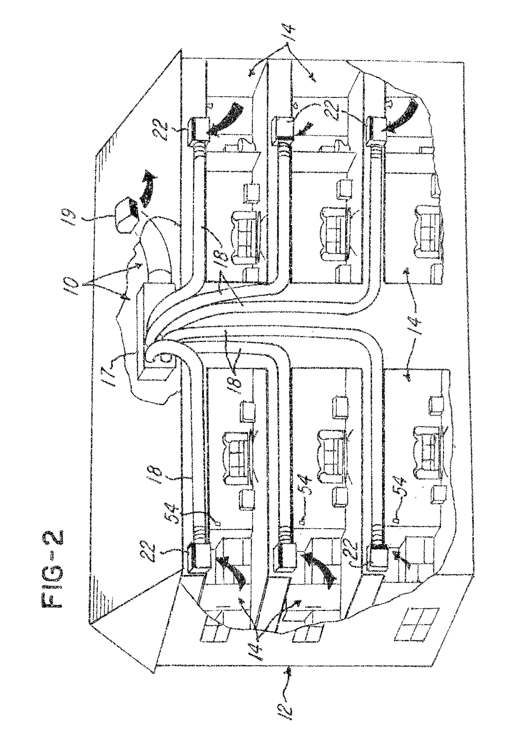
[0045]Referring now to FIGS. 1-3, a zone control ventilation system or passive flow control system 10 for use in the building 12, such as a multi-story commercial building (FIG. 1), multi-story condominium or apartment building (FIG. 2), a residential building (FIG. 3). The system 10 provides a system, apparatus and method for providing on-demand airflow at a demand airflow rate and a passive airflow at a passive airflow rate to a plurality of zones or areas 14 in the manner described later herein.

[0046]The system 10 comprises at least one fan 16 (FIGS. 1 and 3), or the system 10 may comprise a ventilator 17, such as one or more of the multi-port ventilator series (“MPV”) model series MPV ventilator provided by American Aldes Ventilation Corporation of Sarasota, Fla. It should be understood that other suitable ventilators or fans may be used and the invention is not limited by these particular model types.

[0047]The system 10 further comprises a plurality of ducts 18 that are coupled...


PUM


Abstract

A system and method for providing a substantially constant volume exhaust or ventilation air terminal system is shown for controlling exhaust and / or return airflow rates in a system having a central fan or ventilator. The system and method permits zone-by-zone or area-by-area airflow regulation or control in non-demand areas in response to a demand or call for ventilation in demand areas. In one embodiment, the system employs at least one constant airflow controller or regulator situated in a damper. Another embodiment shows a combination of a first constant airflow controller or regulator situated or mounted on a damper with a second constant airflow controller or regulator situated in a duct associated with the damper. In still another embodiment, a constant airflow controller or regulator is provided in a duct, and used in combination with a solid damper.

Description

BACKGROUND OF THE INVENTION[0001]1. Field of the Invention[0002]This invention relates to a method and apparatus for controlling airflow and, more particularly, a method and apparatus for controlling air distribution in fan assisted central exhaust and / or return air ventilating systems.[0003]2. Description of the Related Art[0004]Generally, central ventilation fans and ventilators used for the purpose of removing or exhausting air from areas in a building or structure, such as bathrooms, utility closets, kitchens in homes, offices, and other areas, will simultaneously remove air from fixed inlet terminals connected to the central ventilation fan whenever the fan is operating. Whether the fan operates intermittently or continuously, this results in excessive energy consumption as a result of removing heated and conditioned air from spaces that may not require ventilation simply because the demand for ventilation exists in one or more of the areas.[0005]Previous attempts to limit a ce...

Claims


Application Information

Patent Timeline
Patent Type & Authority Patents(United States)
IPC IPC(8): F24F13/10F24F7/06F24F13/08F24F11/75
CPCF24F11/0001G05D7/0688F24F11/047F24F2140/40F24F11/75Y10T137/86944Y02B30/70
Inventor DIETZ, DENNIS R.HARRELL, JOHN ROBERTSHACKELFORD, DWIGHT RAY
Owner AMERICAN ALDES VENTILATION CORP
Why Eureka
Try Eureka