Separator assembly

a technology of separator assembly and separator chamber, which is applied in the direction of liquid separation agent, filter regeneration, dispersed particle filtration, etc., can solve the problems of lower system efficiency and higher system operating cost, so as to reduce the re-entrainment of material, minimise the disturbance of gas flow, and improve the efficiency of the separator assembly

Active Publication Date: 2010-08-03
PARKER HANNIFIN LTD HEMEL HEMPSTEAD
View PDF54 Cites 37 Cited by
  • Summary
  • Abstract
  • Description
  • Claims
  • Application Information

AI Technical Summary

Benefits of technology

[0008]It is an advantage of the present invention that the use of a liner sleeve can improve the efficiency of a separator assembly. For example, the use of a liner sleeve can reduce the re-entrainment of material separated from the gas stream, back into the gas stream. This is because the inside wall of the body part is made from materials which provide the necessary strength required to withstand internal pressures resulting from the flow of gas through the assembly. The properties of the material from which the wall of the body part is made are such that the material removed from the gas stream can tend to cling to the inside wall, rather than falling down the inside wall past the shield to the quiet space, and so gives rise to the possibility of the material becoming re-entrained in the gas stream. The liner sleeve does not need to have the strength and rigidity of the body part. Accordingly, the liner sleeve can be made from materials having properties which reduce the tendency of the material to cling to the liner sleeve, thereby reducing the chance of the material becoming re-entrained in the gas stream. Also, many different types of liner sleeve can be made having different properties. Accordingly, a liner sleeve can be selected for a separator apparatus depending on the application in which the separator assembly is to be used, so that the properties of the liner sleeve are most suited to that application.
[0009]Preferably, the liner sleeve extends completely annularly around the inside wall of the body part. Accordingly, the liner sleeve can in the form of a tubular structure with a closed-loop cross-section. Optionally, the liner sleeve can be made from a sheet of material that can be wrapped around to form a tubular structure having an overlapping cross-section.
[0010]Preferably, the outer side of the liner sleeve is shaped and sized so that it is a snug fit within the housing body part.
[0011]Preferably, the liner sleeve extends from the face of the shield which is directed toward the upper end of the housing to a point proximal the upper end of the body part. Preferably, the liner sleeve extends along the length of the body part for at least 50% of the distance between the face of the shield which is directed toward the upper end of the housing and the upper end of the body part, more preferably at least 75%. Most preferably, the liner sleeve extends from the face of the shield which is directed toward the upper end of the housing to the upper end of the body part.
[0012]Preferably, the liner sleeve is located in the body part of the housing so that it can be removed from the body part. This is advantageous as it provides for the removal, cleaning, maintenance and interchanging of the liner sleeve.
[0013]Preferably, the liner sleeve is approximately round, especially approximately circular, in shape when viewed from above. This can help to minimise disturbance of the flow of gas due to discontinuities in the path defined by the liner sleeve. It has been found that a circular liner sleeve can help to maintain the helical flow of gas, thereby maintaining the separating property of helical flow of gas caused by centrifugal force. Further, a circular shaped liner sleeve can provide less resistance to a helical gas stream flowing within it. As a result, it has been found that the pressure drop experienced across the separator assembly is less with a circular liner sleeve.

Problems solved by technology

Typically, the higher the pressure drop across a separator assembly in a compressed gas system, the lower the efficiency of the system and the higher the operating costs of the system.

Method used


Image

  • Separator assembly
  • Separator assembly
  • Separator assembly

Examples


Embodiment Construction

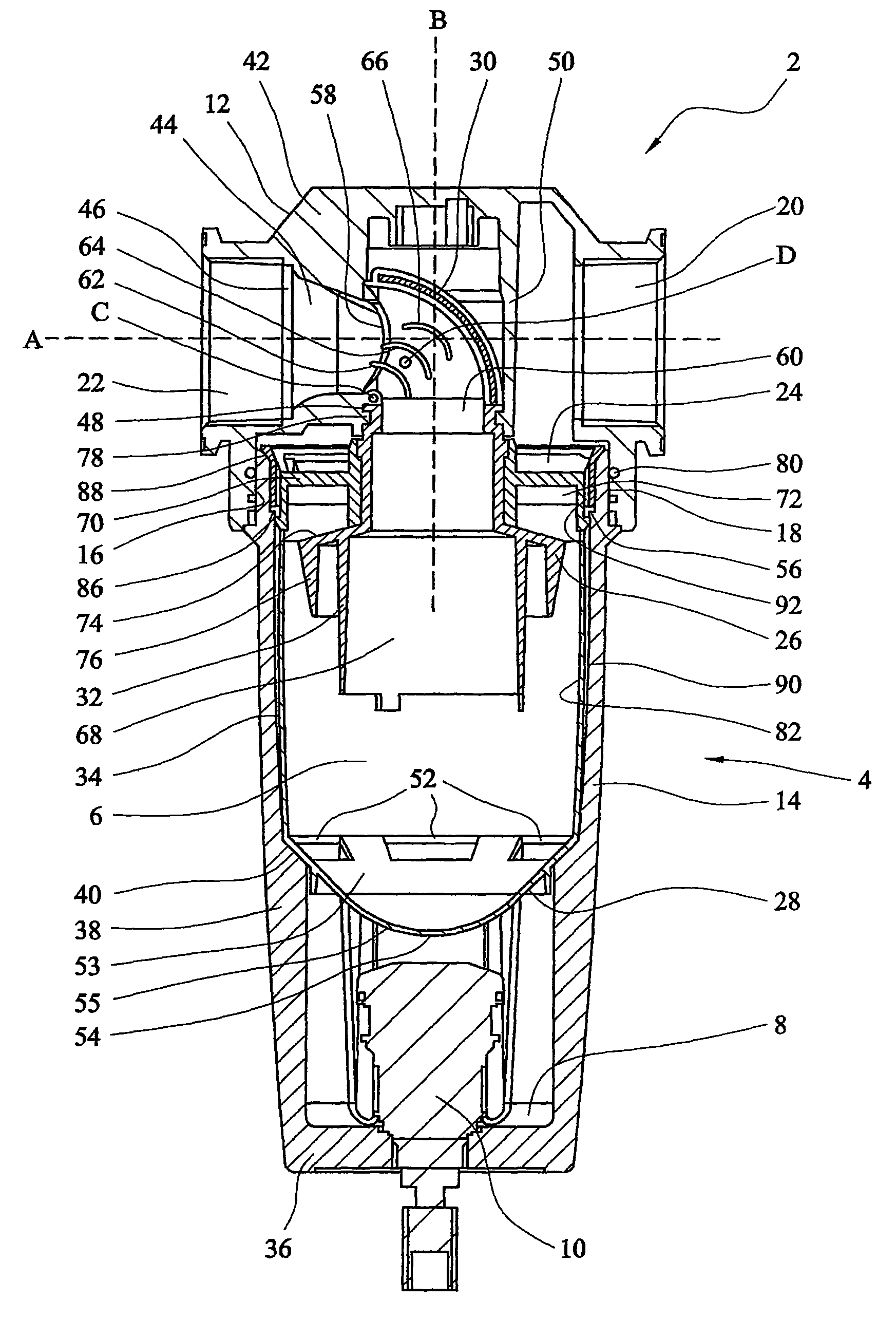
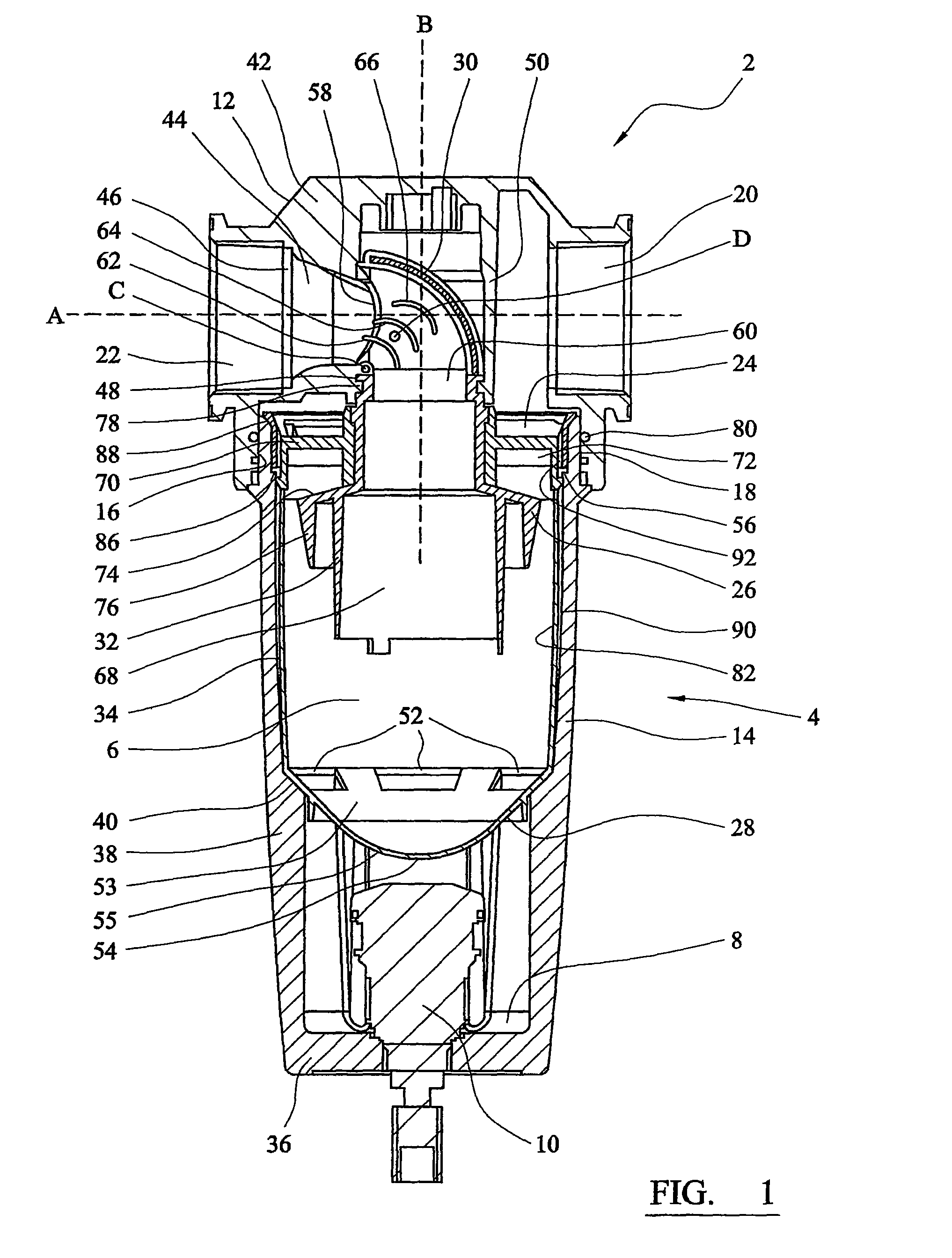
[0080]Referring to the drawings, FIG. 1 shows a separator assembly 2, which comprises a housing 4 defining an inner volume 6. The housing 4 comprises a head part 12, and a body part 14 which can be connected to one another by means of cooperating screw threads at their interfaces 16, 18. The housing 4 further comprises inlet 20 and outlet 22 ports located in the head part 12, for gas to enter and exit the separator assembly 2, a reservoir 8 located at a second end of the housing opposite the first end, and a liquid drainage port 10. The separator assembly further comprises a first flow director 24, a second flow deflector 26, a shield 28, a second flow conduit device 30 which includes a conduit portion 32, all located within the body part 14 of the housing 4.

[0081]The head part 12 and body part 14 are formed from a metallic material, especially aluminium or an alloy thereof. They can be formed by machining or by techniques such as casting.

[0082]The body part 14 comprises a cylindric...


PUM

PropertyMeasurementUnit
angleaaaaaaaaaa
angleaaaaaaaaaa
perimeteraaaaaaaaaa

Abstract

A separator assembly for removing material that is entrained in a gas stream. The separator assembly comprises a housing having a head part which provides the upper end of the housing and a body part which provides the lower end of the housing. The separator assembly also comprises a shield which extends across the housing towards the lower end thereof so as to leave a collection space between it and the lower end in which material that is separated from the gas stream can collect. There is at least one opening in or around the shield through which the material can flow past the shield into the collection space. The separator assembly further comprises a liner sleeve which covers at least a part of the inside wall of the body part between the shield and the upper end of the body part.

Description

CROSS REFERENCE TO RELATED APPLICATIONS[0001]This application is continuation of copending International Application No. PCT / GB06 / 002727 filed Jul. 21, 2006, which designated the United States, the disclosure of which is incorporated herein by reference, and which claims priority to Great Britain Patent Application Nos. 0524181.5 filed Nov. 28, 2005; and 0515266.5, filed Jul. 26, 2005.BACKGROUND OF THE INVENTION[0002]The present invention relates to a separator assembly for removing material that is entrained in a gas stream such as liquid in an aerosol form.SUMMARY OF THE INVENTION[0003]Removal of material from a gas stream can be required to ensure that the gas is sufficiently clean for a subsequent application, or to minimise adverse effects of impurities on components of the system. For example, removal of compressor oil can be required to minimise chemical contamination and accumulation on valves which might lead to malfunction of the valves, and removal of particulate solid ma...

Claims


Application Information

Patent Timeline
Patent Type & Authority Patents(United States)
IPC IPC(8): B01D45/00B01D45/06B01D45/16
CPCB01D45/06B01D45/16B04C5/103B04C5/187Y10S55/46Y10S55/17
Inventor LANE, BRIANBITTLE, STEPHENTROWSDALE, RAY
Owner PARKER HANNIFIN LTD HEMEL HEMPSTEAD
Why Eureka
Try Eureka