Organic electroluminescent devices and composition
a technology of electroluminescent devices and organic materials, applied in the direction of discharge tube luminescnet screens, other domestic articles, natural mineral layered products, etc., can solve the problems of performance limitations that have been a barrier to many desirable applications, and achieve low drive voltage, good operation life, good luminance efficiency
- Summary
- Abstract
- Description
- Claims
- Application Information
AI Technical Summary
Benefits of technology
Problems solved by technology
Method used
Image
Examples
example 1
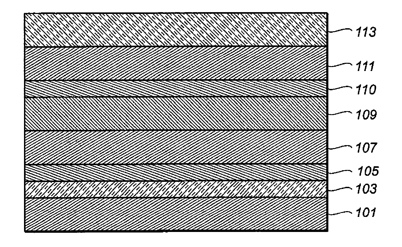
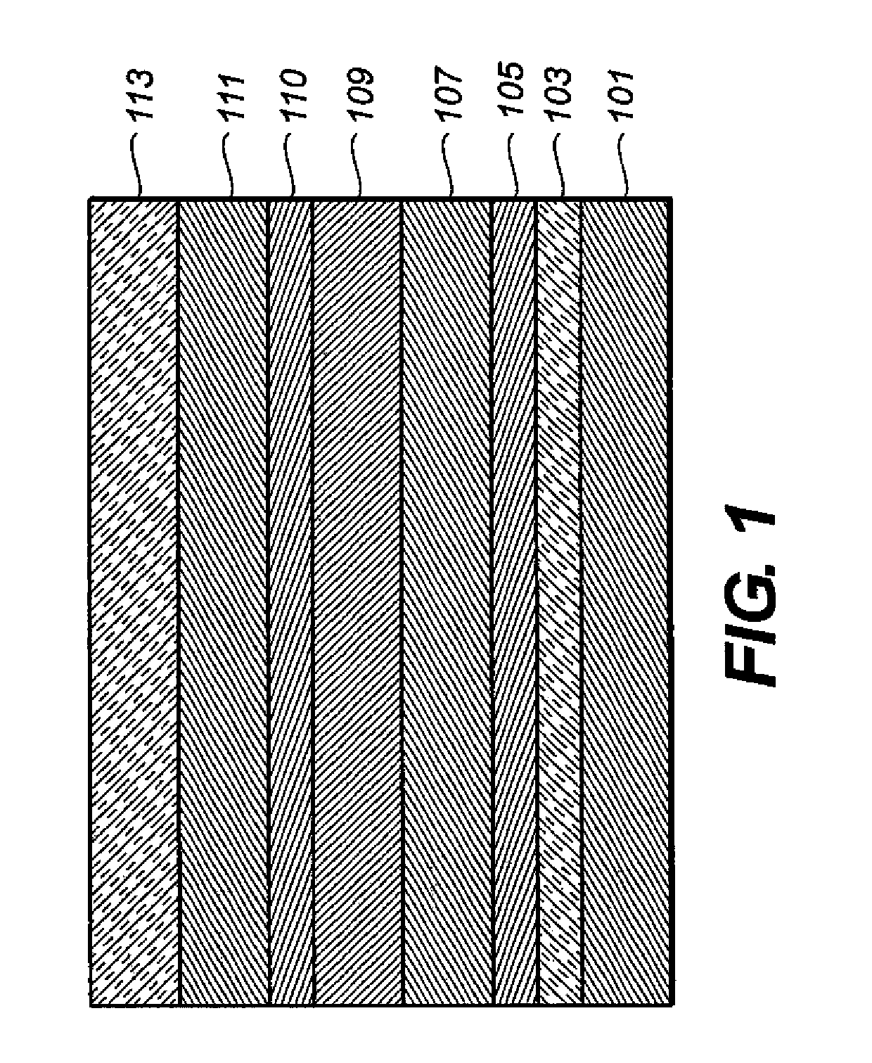
[0192]These samples employ the tris C^N-cyclometallated Iridium compound, fac-tris(1-phenyl-isoquinolinato-N^C)Iridium(III) (Ir(1-piq)3, compound 2b), and the bis C^N-cyclometallated dopant, bis(1-phenyl-isoquinolinato-N^C)Iridium(III)(acetylacetonate) (Ir(1-piq)2(acac)), each having a triplet energy of about 2.08 eV estimated from emission spectra obtained at room temperature from a film of polymethylmethacrylate doped with the compound.[0193]Sample 1-1: An OLED was vapor deposited on a glass substrate to have the following structure of layers: ITO / NPB (75 nm) / Alq+8% Ir(1-piq)3 / Alq (40 nm) / MgAg (220 nm).[0194]Sample 1-2: An OLED was vapor deposited on a glass substrate to have the following structure of layers: ITO / NPB (75 nm) / Alq+8% Ir(1-piq)3 / TH-1 (10 nm) / Alq (40 nm) / MgAg (220 nm).[0195]Sample 1-3: Same as 1-1 except the dopant was Ir(1-piq)2(acac), also at 8%.[0196]Sample 1-4: An OLED was vapor deposited on a glass substrate to have the following structure of layers: ITO / NPB (75...
example 3
[0213]For the following set of five comparison and five invention devices, the ITO on glass substrates were had resistivity in the range 100 to 110 ohms / sq.
[0214]Comparison samples: Five different OLEDs were fabricated with the following layer structure incorporating TH-1 as the neat host for the red Ir(1-piq)3 dopant: ITO / NPB (115 nm) / TH-1+ Ir(1-piq)3 (35 nm) / TH-1 (10 nm) / Alq(40 nm) / MgAg (220 nm). The Ir(1-piq)3 dopant concentration was varied from 1 to 10% to produce five different samples.
[0215]Invention samples: OLEDs were fabricated in the same manner as the preceding comparisons except the host for the Ir(1-piq)3 dopant was a mixture formed by co-evaporating TH-1 and NPB at rates to produce a layer containing 15 weight % NPB relative to TH-1. Again the concentration of Ir(1-piq)3 dopant was varied from 1 to 10% relative to the total of the mixed host materials to produce five device samples. The NPB concentration of 15% was found through prior experimentation to give near opti...
example 4
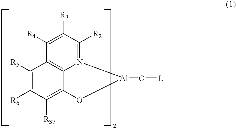
[0219]This example employs the orange phosphorescent dopant fac-tris(3-phenyl-isoquinolinato-N^C)Iridium(III) (Ir(3-piq)3, compound 2c) having a triplet energy of about 2.3 eV and further illustrates the importance to the present invention of selecting the aluminum bis-(2-substituted)oxinoid compound bearing a third ligand comprising an aromatic-oxy group based on its triplet energy relative to that of the desired phosphorescent dopant.[0220]Sample 4-1: An OLED was fabricated with the following layer structure: ITO / NPB (115 nm) / (TH-1+15% NPB)+6% Ir(3-piq)3 (35 nm) / TH-1 (10 nm) / Alq (40 nm) / MgAg (220 nm).[0221]Sample 4-2: Same as sample 3-1 except TH-3 was used instead of TH-1.
The results are shown in Table 5.
[0222]
TABLE 5SampleV @ 2 mA / cm2CIE xCIE yYield (Cd / A)4-17.860.550.447.64-27.970.540.4516.3
[0223]The results in table 5 show that sample 4-1 according to the invention with an aluminum oxinoid host having triplet energy (2.36 eV; see Table 1) slightly above that of the orange phos...
PUM
| Property | Measurement | Unit |
|---|---|---|
| triplet energy | aaaaa | aaaaa |
| thick | aaaaa | aaaaa |
| thickness | aaaaa | aaaaa |
Abstract
Description
Claims
Application Information
 - R&D
- Intellectual Property
- Life Sciences
- Materials
- Tech Scout
- Unparalleled Data Quality
- Higher Quality Content
- 60% Fewer Hallucinations
Browse by: Latest US Patents, China's latest patents, Technical Efficacy Thesaurus, Application Domain, Technology Topic, Popular Technical Reports.
© 2025 PatSnap. All rights reserved.Legal|Privacy policy|Modern Slavery Act Transparency Statement|Sitemap|About US| Contact US: help@patsnap.com


