Electrostatic discharge protection for microwave guided wave structure

a technology of electromagnetic discharge protection and guided wave structure, which is applied in emergency protective arrangements for limiting excess voltage/current, relays, therapy, etc., can solve the problems of limiting the utility of such devices above 1 ghz, affecting the desired operation of microwave structures and circuits, and a large capacitan

Inactive Publication Date: 2010-08-03
POPEK MARC H
View PDF2 Cites 0 Cited by
  • Summary
  • Abstract
  • Description
  • Claims
  • Application Information

AI Technical Summary

Benefits of technology

[0006]The present invention provides an effective and practical solution to the problem of electrostatic discharge protection for microwave structures and circuits of the coplanar, microstrip, and stripline type, for example. The invention utilizes a protection device that can be added to existing guided wave structures (or during manufacture of such structures) with minimal disruption of the structures and with minimal interference with their normal operation. In a preferred form, a protection device of the invention includes an insulating base that bridges a space between a signal conductor and a ground conductor (e.g., ground plane) or a space between a signal conductor and a conductive member that extends from the ground conductor. The insulating base of the protection device supports a structure that provides an electrostatic discharge path for discharging electrostatic charges that build up on the signal conductor to a predetermined voltage level. More particularly, an electrostatic discharge protection device of the invention uses an insulating material (e.g., polyester) applied as a liquid film that sets, and onto which a plurality of metal particles are dispersed before the film sets, so that the particles adhere to the film.

Problems solved by technology

Prior protection devices, such as zener diodes and variable resistors, have a rather large capacitance that interferes with the desired operation of microwave structures and circuits.
The large capacitance and the inductance of the packaging leads create a self resonance that limits the utility of such devices above 1 GHz.
Moreover, the packaging and mounting of the prior art protection devices further limit their use.

Method used


Image

  • Electrostatic discharge protection for microwave guided wave structure
  • Electrostatic discharge protection for microwave guided wave structure
  • Electrostatic discharge protection for microwave guided wave structure

Examples


Embodiment Construction

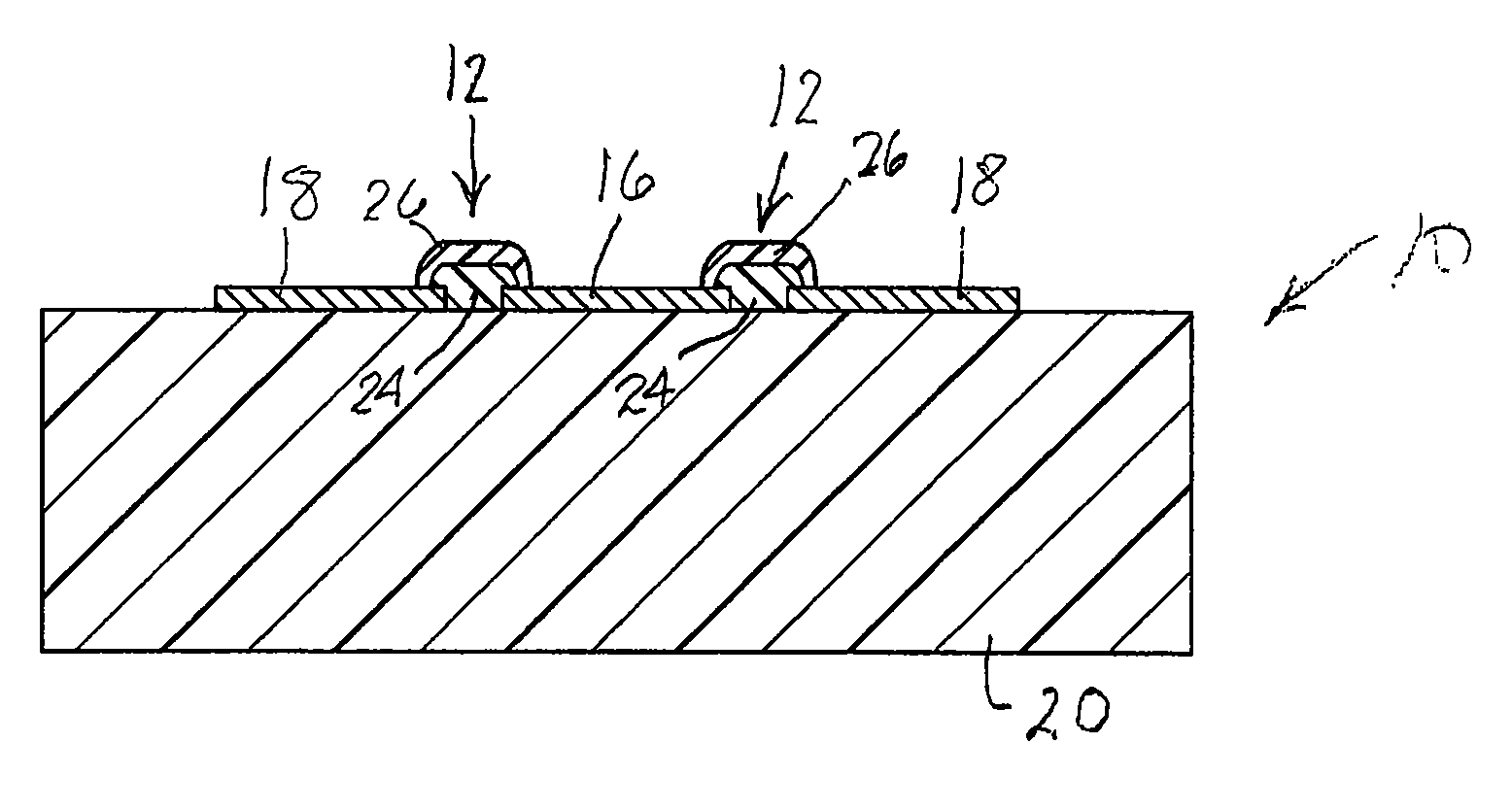
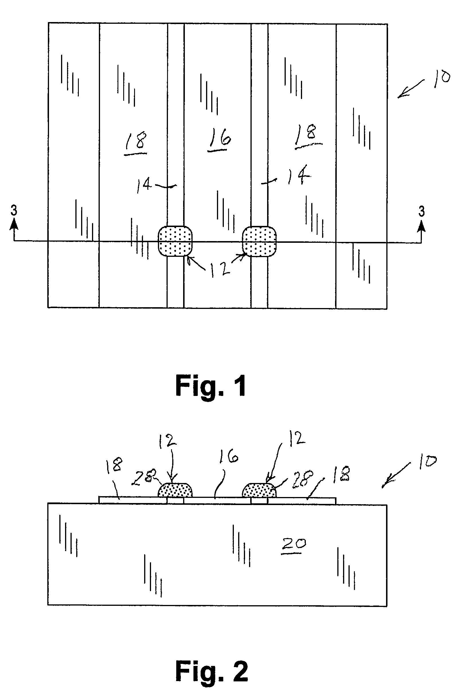
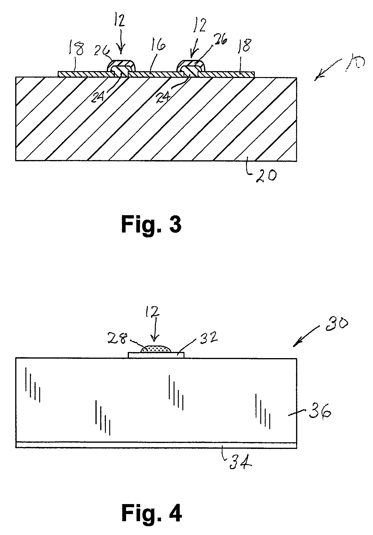
[0014]The invention will first be described in its application to electrostatic discharge protection of a coplanar type microwave structure 10, shown in FIGS. 1-3. In this embodiment, there are two electrostatic discharge protection devices 12 that bridge spaces 14 between a signal conductor 16 and a pair of ground conductors 18 at opposite edges of the signal conductor, all being supported by a dielectric 20. The construction of the coplanar microwave structure (as well as others to be described hereinafter) is conventional and need not be described in detail.

[0015]Each electrostatic discharge protection device has a body that includes an insulating base supporting a structure that provides an electrostatic discharge path for discharging electrostatic charges that build up on the signal conductor to a predetermined voltage level. In a preferred form, the base comprises two layers of insulation, a first of which 24 is adhered to the structure to be protected and the second of which ...


PUM


Abstract

Electrostatic discharge protection for guided wave microwave structures is provided by a protection device that imposes minimal disruption on the microwave structures and negligible interference with the normal operation of the structures. The protection device provides a discharge path between a signal conductor and a ground conductor when electrostatic charges on the signal conductor reach a predetermined voltage level. The protection device includes an insulating base that bridges a space between the signal conductor and the ground conductor and that supports a dispersion of metal particles adhered to the base.

Description

CROSS-REFERENCE TO RELATED APPLICATION[0001]This application claims the benefit of Provisional application Ser. No. 10 / 699,222 filed Jul. 13, 2005, incorporated herein by reference.BACKGROUND OF THE INVENTION[0002]This invention is concerned with electrostatic discharge protection for microwave structures and circuits, more particularly, with devices and methods that provide electrostatic discharge protection with minimal disruption and interference with the structure and operation of microwave guided wave structures.[0003]Electrostatic discharge protection devices for electronic systems operating at frequencies below 1 GHz are well known. More recently, there has been a need for providing electrostatic discharge protection in higher frequency (microwave) structures and circuits that operate above 1 GHz (e.g., between 1 GHz and 20 GHz). Waveguide structures operating in the microwave regime include microstrip, stripline, and coplanar guide structures, for example. Prior protection d...

Claims


Application Information

Patent Timeline
Patent Type & Authority Patents(United States)
IPC IPC(8): H05F3/04
CPCH05K9/0056A61N1/14
Inventor POPEK, MARC H.
Owner POPEK MARC H
Why Eureka
Try Eureka