
Fast three dimensional recovery method and apparatus

a three-dimensional recovery and fast technology, applied in the field of stereo vision, can solve the problems of computational cost, bottleneck on production lines, poor results among other models widely used,

Inactive Publication Date: 2010-08-03
PREFIXA VISION SYST DE C V
View PDF5 Cites 23 Cited by
  • Summary
  • Abstract
  • Description
  • Claims
  • Application Information

AI Technical Summary

Benefits of technology

"The invention provides a method and apparatus for acquiring stereo images that fulfill the reciprocity reflectance property to recover depth information of an object placed into the field of view of a single or multi stereo cameras array. This allows for three dimensional modeling of objects regardless their reflectance distribution. The system uses an extended binocular approach which does not have any restriction related with the projection geometry or the camera setup configuration. The system requires a stereo and radiometric calibration process prior to the capture of object images. The calibration process includes the use of a stereo and radiometric calibration pattern, a stereo rectification process, and an algorithm for three dimensional recovery. The system has a stereo head with an interior illumination control that allows for the automatic commutation of the stereo light sources to fulfill the reciprocity property of the images. The system is fully automatic, easy to use, and has a simple setup and calibration process. The system simplifies the light control to obtain stereo images with symmetrical intensity curves. Additionally, an embodiment of the imaging apparatus allows for a stereo camera configuration with a parallel and convergent optical axis."

Problems solved by technology

Obtaining dense and accurate three-dimensional models is computationally expensive and can cause a bottleneck on production lines.
Although Tsai's model is widely used in computer vision, it produces the poorest result among other models widely used.
A limitation of the DLT model is that it does not take care of lens distortion, which may severely affect the measurement accuracy.
One problem with Haralick's standard solution is that the non-linear equations make it impossible to get a direct solution.
This means a good guess of initial parameters must be available and it cannot be guaranteed that the iteration will get a convergent result.
The main disadvantage of structured lighting methods is that they require several image acquisitions (in the order of 4 to 32) under different lighting conditions in order to obtain a dense depth map, so that, these recovery techniques are computationally expensive methods, and they are not presently practical for fast 3D acquisition applications like production lines inspection or object modeling
Furthermore, textureless and flat surfaces cannot be recovered using either active or passive conventional stereo techniques.
Unfortunately, this article does not illustrate how such a technique can be easily integrated with the calibration process.

Method used


Image

  • Fast three dimensional recovery method and apparatus
  • Fast three dimensional recovery method and apparatus
  • Fast three dimensional recovery method and apparatus

Examples


Embodiment Construction

[0044]System Configuration

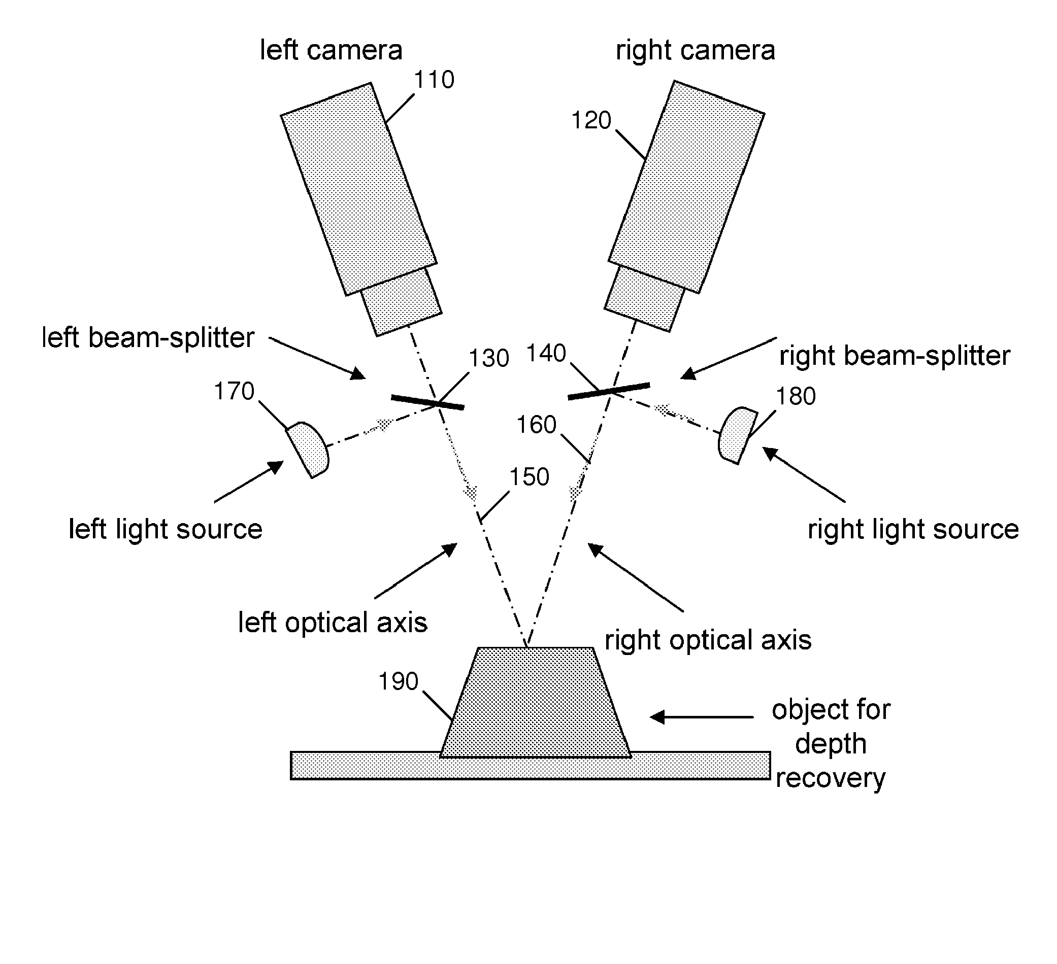
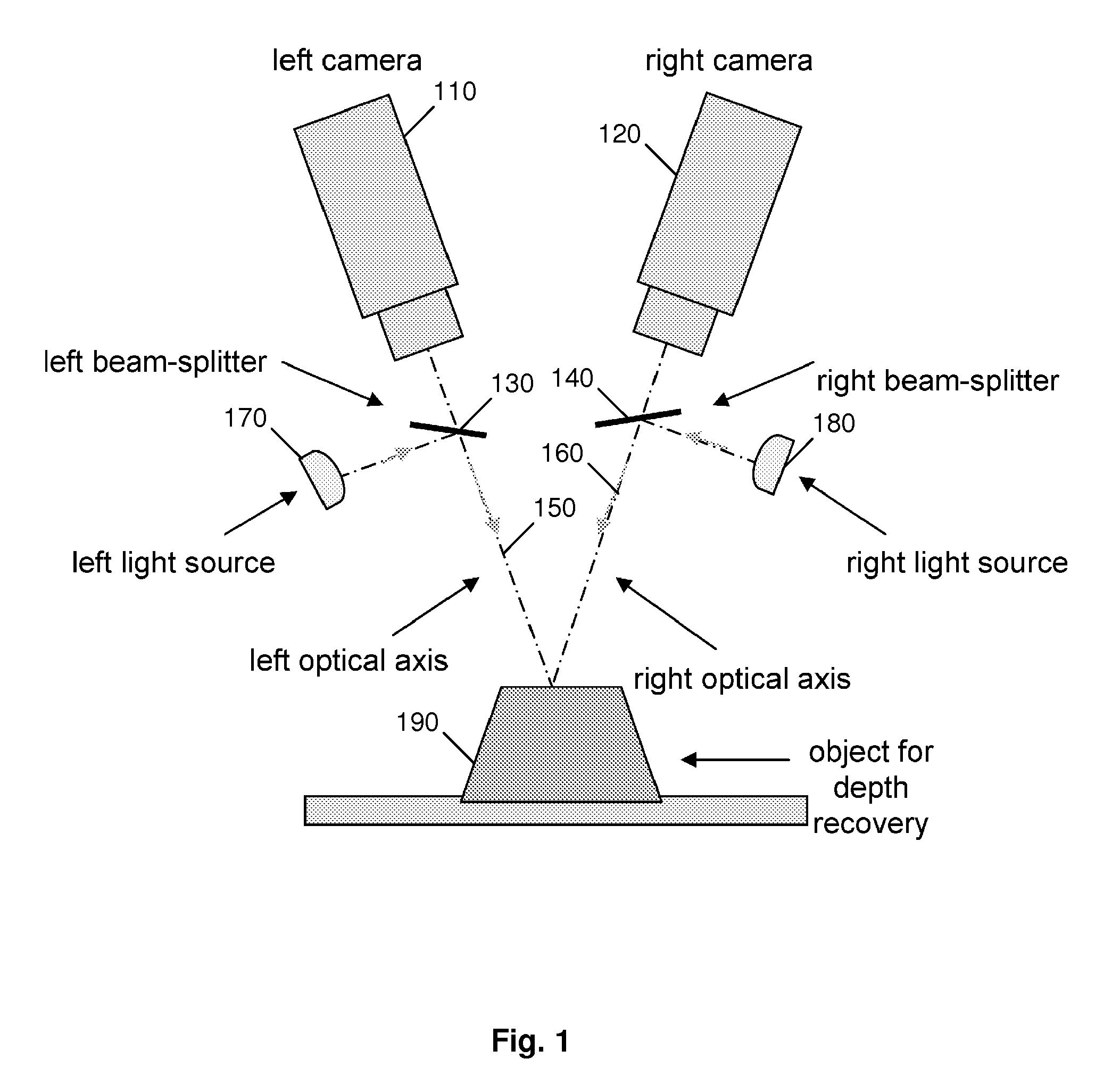
[0045]FIG. 1 illustrates the general principle of the invention. Left camera 110 and right camera 120 capture images from object 190. A left light source 170 and a left beam-splitter 130 are utilized so that object 190 is illuminated along left optical axis 150 when an image is captured by right camera 120, and similarly right light source 180 and right beam-splitter 140 are utilized to illuminate object 190 along right optical axis 160 when an image is captured by left camera 110.

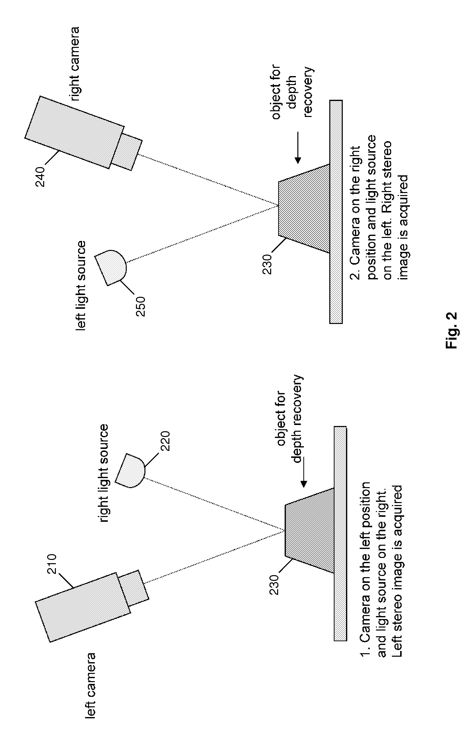
[0046]The image acquisition process is illustrated in more detail in FIG. 2. Left camera 210 captures an image of object 230 when illuminated by right light source 220. In this manner the left stereo image is acquired. Right camera 240 captures an image of object 230 when illuminated by left light source 250. In this manner the right stereo image is acquired. After both images have been acquired, the present invention can recover depth information, as is described in detail below....


PUM


Abstract

The present invention comprises a method and an apparatus for three dimensional modeling to allow dense depth maps to be recovered, without previous knowledge of the surface reflectance, from only a single pair of stereo images. Several initial steps are performed for stereo and radiometric calibration and rectification for obtaining accurate results. The apparatus for the stereo images acquisition includes internal light sources, these are automatically commuted by a illumination control in order to fulfill the reciprocity property, a stereo camera head composed by the necessary optics to acquire the reciprocal stereo images and a compatible PC interface. The invention is faster than other systems since it requires only two images for obtaining a dense depth model of objects with an arbitrary surface reflectance distribution allowing the system to be used in a wide range of applications such as metrology, quality control, medical and dynamic three dimensional modeling.

Description

FIELD OF THE INVENTION[0001]The present invention relates to stereo vision, particularly to a method and an apparatus for stereo and radiometric calibration, a three dimensional stereo technique and depth map calibration process to obtain accurate dense depth maps without previous knowledge of surface reflectance.BACKGROUND[0002]Stereo vision consists of three-dimensional data recovery of an object viewed from two or more view-points. Some fields of application for stereo vision are industrial, such as quality control of production lines, where concepts of inspection and sampling to remove defective products are required. Medicine is another important field where highly accurate models are required by specialists. Obtaining dense and accurate three-dimensional models is computationally expensive and can cause a bottleneck on production lines.[0003]Stereo vision generally involves several stages. First, a calibration process is necessary. This process comprises both stereo and radiom...

Claims


Application Information

Patent Timeline
Patent Type & Authority Patents(United States)
IPC IPC(8): G06K9/00
CPCG06T7/002G06T7/0073G06T7/0075G06T2207/10012G06T7/85G06T7/586G06T7/593
Inventor ARIAS-ESTRADA, MIGUELMORALES-REYES, ALICIAROSAS-CHOLULA, MARIA LUISASOSA-RAMIREZ, GERARDO
Owner PREFIXA VISION SYST DE C V
Learn More