Method of operating a plug-in hybrid electric vehicle
a hybrid electric vehicle and plug-in technology, applied in the field of plug-in hybrid electric vehicle operation, can solve the problems of purely electric vehicles lacking an on-board means to recharge, and the cost of recharging is proportional to the cost of consumable fuel, and achieve the effect of disabling the operation of plug-in hybrid electric vehicl
- Summary
- Abstract
- Description
- Claims
- Application Information
AI Technical Summary
Benefits of technology
Problems solved by technology
Method used
Image

Examples
Embodiment Construction
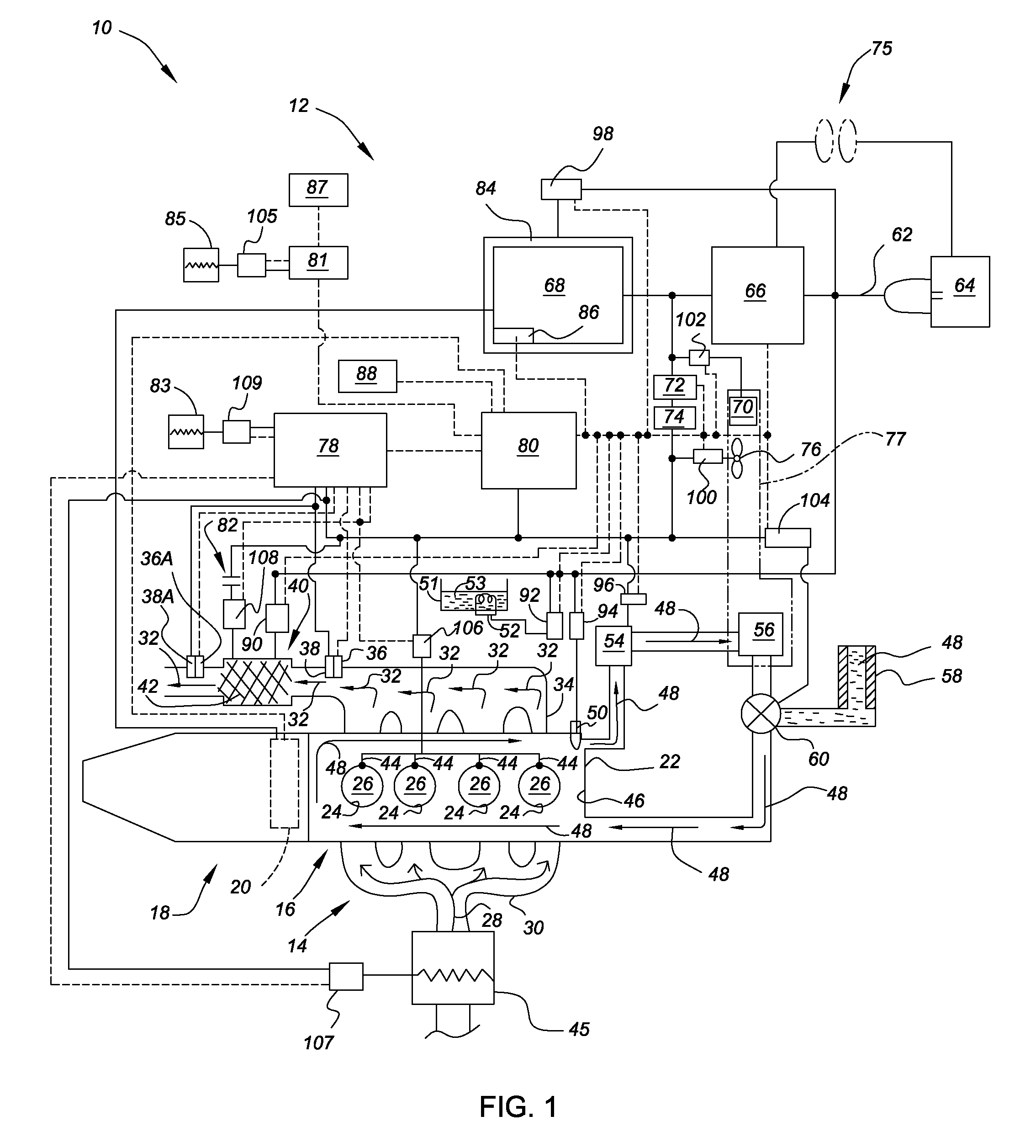
[0012]Referring to FIG. 1, there is shown a portion of a plug-in hybrid electric vehicle, generally indicated at 10. The plug-in hybrid electric vehicle 10 includes a control system 12 and a hybrid powertrain 14. The hybrid powertrain 14 includes an internal combustion engine 16, such as a spark-ignited or a compression-ignited engine, having a transmission 18 operatively connected thereto. The internal combustion engine 16 of FIG. 1 is a compression ignited diesel engine; however, those skilled in the art will recognize the claimed invention may be applied to hybrid powertrains incorporating a spark-ignited engine while remaining within the scope of that which is claimed. The internal combustion engine 16 provides torque to the transmission 18, which in turn, provides the requisite driving force to effect movement of the plug-in hybrid electric vehicle 10. At least one motor 20 may be provided to effect movement of the plug-in hybrid electric vehicle 10 in conjunction with, or in l...
PUM
 Abstract
Description
Claims
Application Information