Electromagnetic piezoelectric acoustic sensor

a piezoelectric acoustic sensor and piezoelectric technology, applied in the direction of mechanical audible signalling, solid analysis using sonic/ultrasonic/infrasonic waves, magnetic measurement, etc., can solve the problem of reducing sensitivity and interpretation complications, wave penetration still overshoots interfacial chemistry with loss of sensitivity, and provides a sufficiently compact evanescent zone to fully recover biochemical signals

a piezoelectric acoustic sensor and piezoelectric technology, applied in the direction of mechanical audible signalling, solid analysis using sonic/ultrasonic/infrasonic waves, magnetic measurement, etc., can solve the problem of reducing sensitivity and interpretation complications, wave penetration still overshoots interfacial chemistry with loss of sensitivity, and provides a sufficiently compact evanescent zone to fully recover biochemical signals

US7770456B2Inactive Publication Date: 2010-08-10STEVENSON ADRIAN +1

Image

  • Electromagnetic piezoelectric acoustic sensor
  • Electromagnetic piezoelectric acoustic sensor
  • Electromagnetic piezoelectric acoustic sensor

Examples


Embodiment Construction

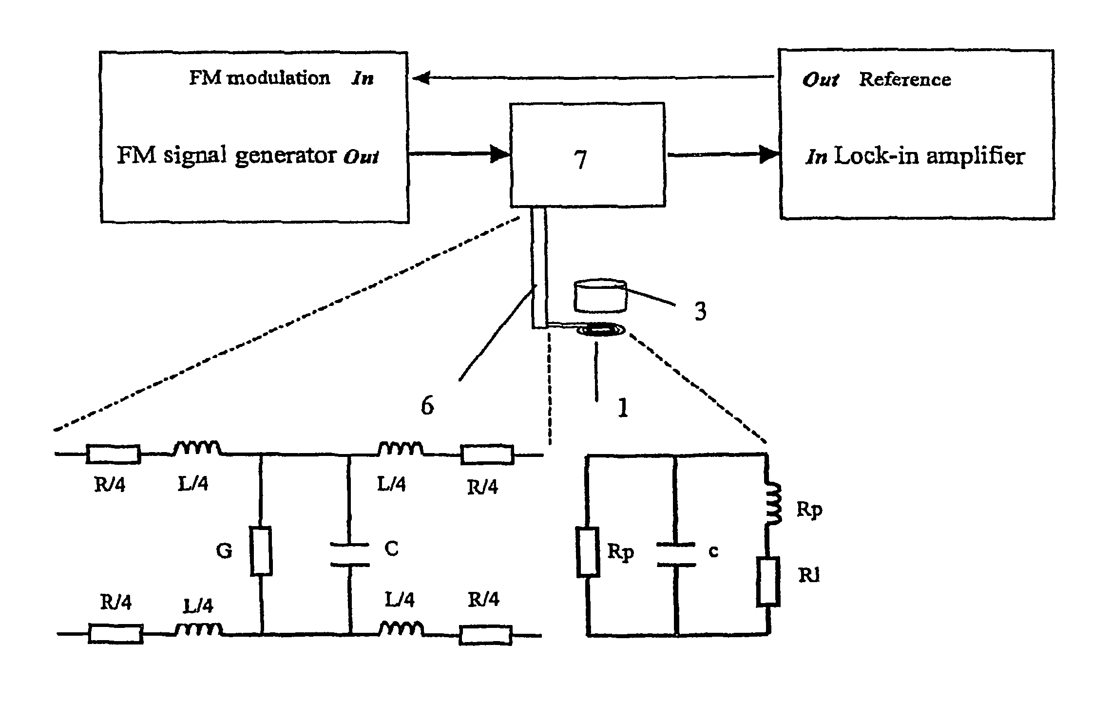
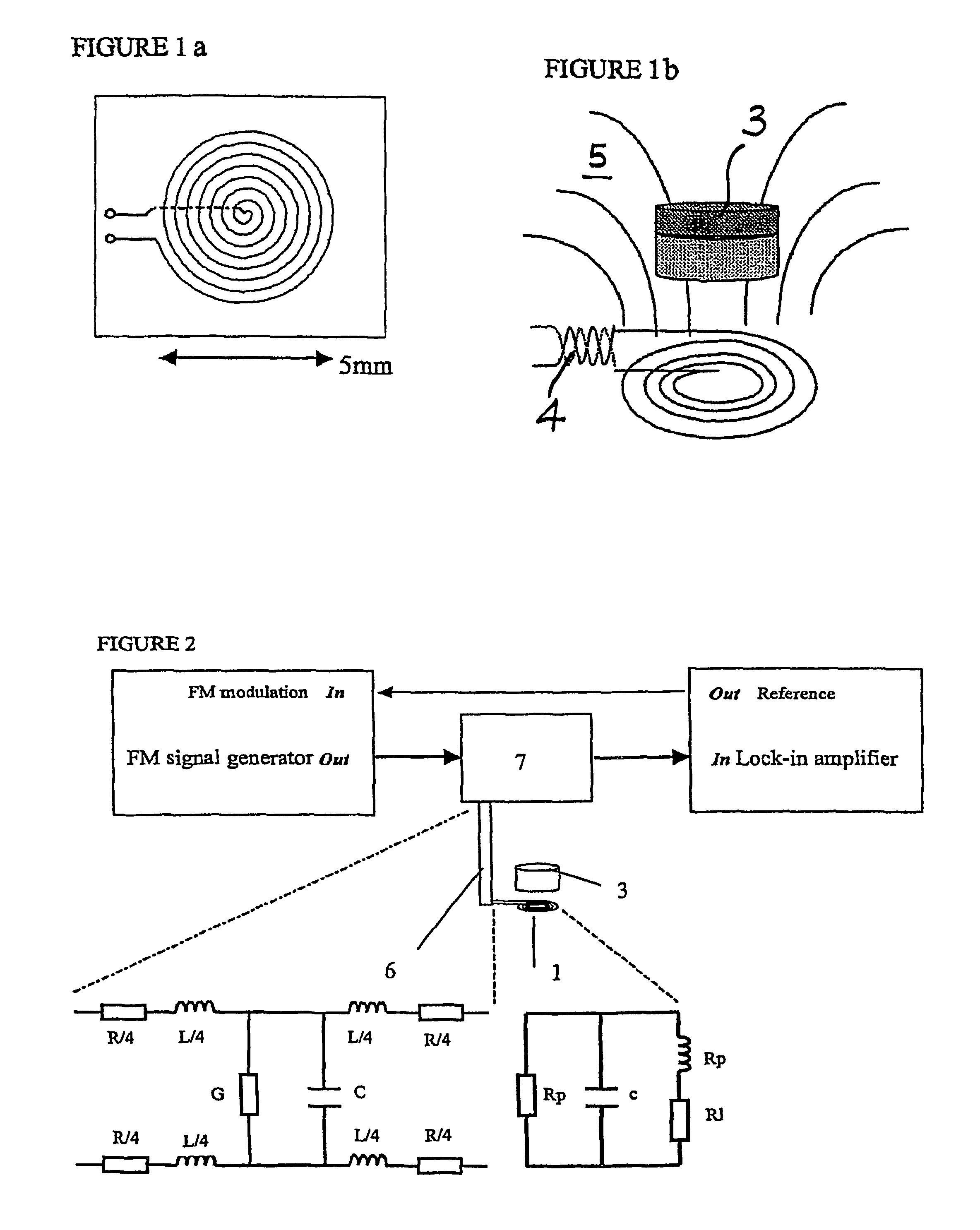
[0031]FIG. 1b and FIG. 2 show an example arrangement in a sensor according to the present invention. A coil 1 receives RF current 4 via a multiply resonant transmission line 6. The electromagnetic field 5 produced by the coil 1 drives a piezoelectric element 3 to produce acoustic waves by electrostriction. The sensing done by the acoustic waves occurs either directly or indirectly. The substance to be detected either adsorbs to the vibrating surface, or a receptor can be attached to the vibrating surface, which is specific to the substance to be detected. When the substance adsorbs, it changes the acoustic spectrum. The coil 1 also acts as a detector which converts the changed electromagnetic field caused by the changed acoustic waves back into a RF current which is detected by a detection circuit, which includes an AM-diode detector 7 in this example.

[0032]The present invention eliminates the need for fine tuning between the transmission line 6 and the coil 1 in order to generate t...


PUM

PropertyMeasurementUnit
harmonic frequenciesaaaaaaaaaa
frequencyaaaaaaaaaa
electromagnetic fieldaaaaaaaaaa

Abstract

An acoustic sensor comprises at least one resonant element. A driver comprises an electrical coupling means and an electromagnetic field source arranged such that the electrical coupling means transfers currents to the electromagnetic field source. The electromagnetic field source produces an electromagnetic field that drives the resonant elements to produce acoustic waves directed to a predetermined part of a test sample. Also provided is an electromagnetic detector for receiving the acoustic spectrum omitted from a test sample and an electrical circuit connected to the drive around detector.

Description

BACKGROUND OF THE INVENTION[0001]1. Field of the Invention[0002]Acoustic sensors which employ resonators have been used as detection devices for biological molecules for the past two decades, exhibiting sensitivity in the ng / ml range. They share with optical devices an ability to produce evanescent waves that propagate a limited distance across the solid liquid interface, so molecular events and processes in the bulk are not detected; only those processes leading to interfacial elasticity, viscosity, viscoelasticity and slippage are detected.[0003]2. The Prior Art[0004]However there are significant problems with these systems. As the dimensions of the molecules of interest range from 5 to 20 nm, a substantial amount (>95%) of acoustic transverse coupling is to the fluid above the chemical interface, essentially outside of the domain of the analysis in which there is interest.[0005]An evanescent sensing region that is significantly thicker than the chemical layer of interest leads...

Claims


Application Information

Patent Timeline
10 Aug 2010
Publication
US7770456B2
IPC
G01R33/20; G01N27/72; G01N27/00
CPC
G01N29/036; G01N2291/014; G01N2291/0256; G01N2291/101
Inventors
STEVENSON, ADRIAN; LOWE, CHRISTOPHER ROBIN