Balloon refolding device

a balloon and balloon technology, applied in the field of medical catheters, can solve the problems of heart muscle deprived of oxygen, patient is prone to suffer angina, and arterial blockage caused by plaque in the arteries of patients can have grave consequences

Active Publication Date: 2010-08-10
BOSTON SCI SCIMED INC
View PDF52 Cites 47 Cited by
  • Summary
  • Abstract
  • Description
  • Claims
  • Application Information

AI Technical Summary

Benefits of technology

[0010]In one particular embodiment, the device may be configured for use on a cutting balloon having a plurality of longitudinally aligned blades that extend radially from the surface of an inflatable balloon. In this embodiment, each elastic member is formed with a slot to allow a respective blade to extend through the elastic member. With this cooperation of structure, the elastic members fold the cutting balloon into a configuration in which the blades become nestled within a pair of adjacent balloon pleats. This nestled configuration prevents the blades from inadvertently incising tissue during a movement of the balloon catheter through the vasculature of a patient.

Problems solved by technology

Arterial blockages caused by the build up of plaque in the arteries of a patient can have grave consequences.
When blood flow is reduced in a coronary artery, the heart muscle becomes deprived of oxygen, and the patient is prone to suffer angina.
In severe cases of coronary artery blockage, the patient can suffer a heart attack.
A particular problem associated with an angioplasty procedure exists during the deflation stage of the balloon, prior to its removal from the artery.
If the balloon fails to deflate in a uniform manner, an irregular bulge in the balloon may cause difficulties in withdrawing the balloon catheter from the artery.
However, the cutting blades used in cutting balloons are extremely sharp (e.g. three to five times sharper than a conventional scalpel), and in the absence of special precautions, have the potential to inadvertently incise non-target tissue during in vivo movement of the cutting balloon to and from a stenosis.

Method used


Image

  • Balloon refolding device
  • Balloon refolding device
  • Balloon refolding device

Examples


Embodiment Construction

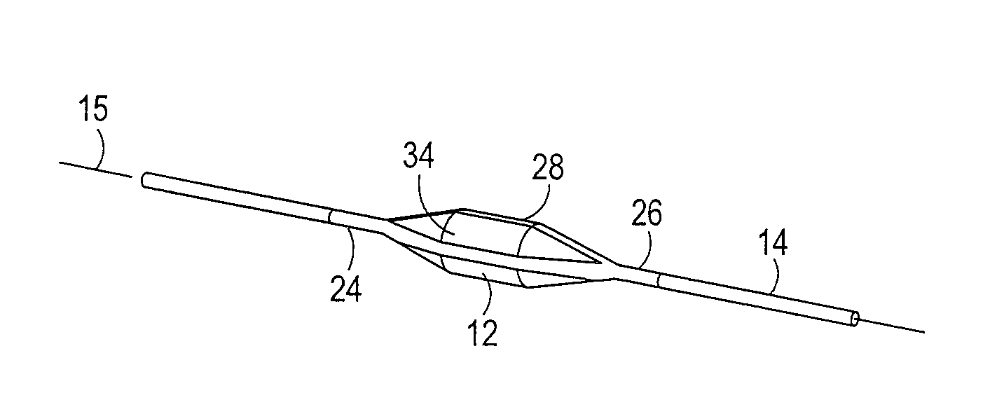
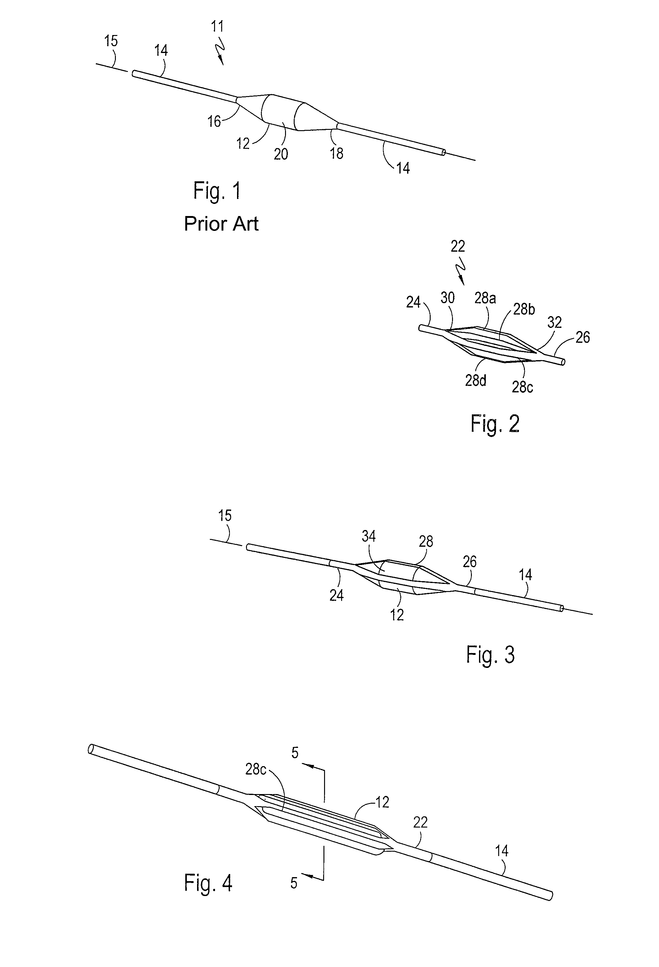
[0022]Referring to FIG. 1, the distal portion of a typical balloon catheter is shown and is generally designated 11. As shown in FIG. 1, the catheter 11 includes an inflatable balloon 12 that is mounted on an elongated catheter tube 14, which defines a longitudinal axis 15. It can be further seen that the exemplary inflatable balloon 12 extends from a distal end 16 to a proximal end 18 and includes a substantially cylindrical working section 20. Those skilled in the pertinent art will appreciate that the catheter tube 14 can be used to establish fluid communication between the inflatable balloon 12 and a fluid pump / fluid source (not shown), which in turn, can be selectively activated to inflate and deflate the balloon 12 from an extracorporeal location. Functionally, the catheter 11 can be used to position the balloon 12 across a stenosis whereupon the balloon 12 can be inflated to revascularize a diseased vessel such as a clogged artery.

[0023]FIG. 2 shows a folding device which is ...


PUM


Abstract

A device for folding a balloon of a balloon catheter onto a catheter tube during a balloon deflation includes a first band positioned on the catheter tube distal to the balloon and a second band positioned on the catheter tube proximal to the balloon. One or more elastic member(s) are attached to and extend between the bands for interaction with the outer surface of the balloon. During a balloon deflation, the elastic members cooperate to fold the balloon into pleats. When used on a cutting balloon, each elastic member is formed with a slot to allow a respective blade of the cutting balloon to extend through the elastic member. The elastic members fold the cutting balloon into a configuration in which each blade becomes nestled within a pair of adjacent balloon pleats to prevent the blade from inadvertently incising tissue during an in-vivo movement of the balloon catheter.

Description

FIELD OF THE INVENTION[0001]The present invention pertains generally to medical catheters. More particularly, the present invention pertains to catheters having inflatable balloons. The present invention is particularly, but not exclusively, useful for folding a balloon onto a catheter tube during a balloon deflation.BACKGROUND OF THE INVENTION[0002]Arterial blockages caused by the build up of plaque in the arteries of a patient can have grave consequences. Specifically, the build up of plaque in arteries can reduce and eventually block blood flow through the affected vessel. When blood flow is reduced in a coronary artery, the heart muscle becomes deprived of oxygen, and the patient is prone to suffer angina. In severe cases of coronary artery blockage, the patient can suffer a heart attack.[0003]Many modern surgical techniques have been developed to alleviate the stenoses that are formed when plaque builds up in a patient's arteries. For example, a large number of balloon angiopla...

Claims


Application Information

Patent Timeline
Patent Type & Authority Patents(United States)
IPC IPC(8): A61M29/00A61B17/22A61F2/958
CPCA61B17/22A61B17/320725A61M25/1038A61B2017/22061A61B2017/320741A61M2025/1004
Inventor KUNIS, CHRISTOPHER G.
Owner BOSTON SCI SCIMED INC
Why Eureka
Try Eureka