

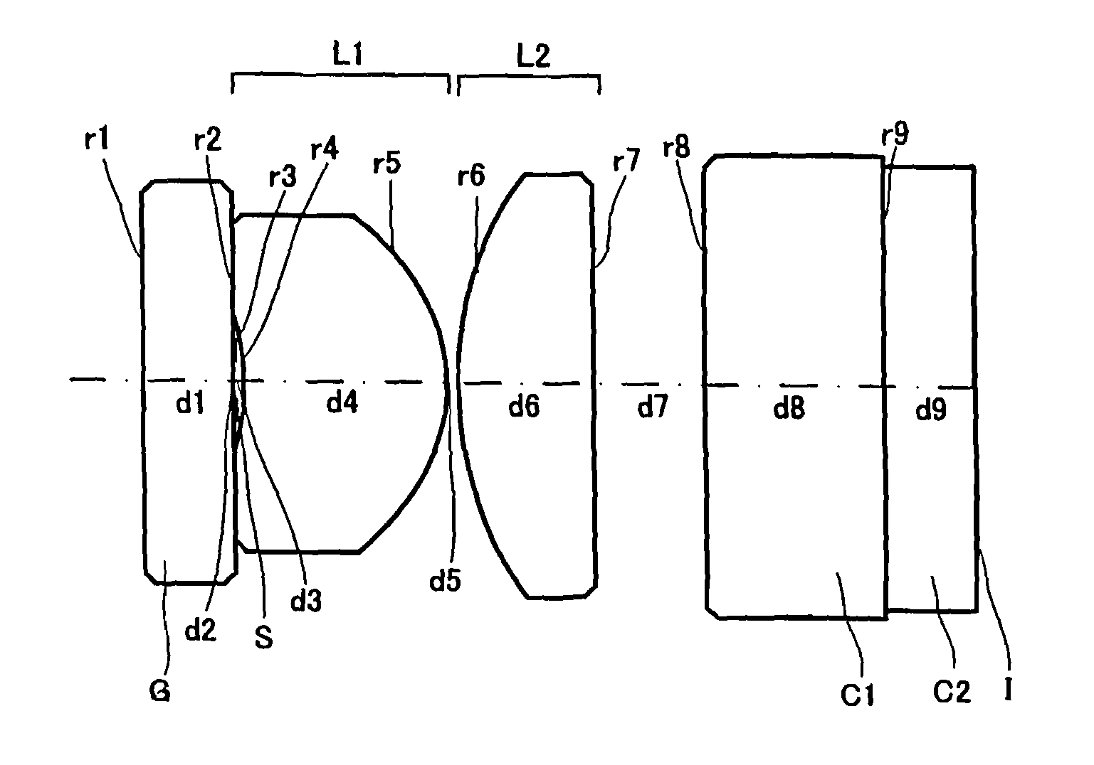
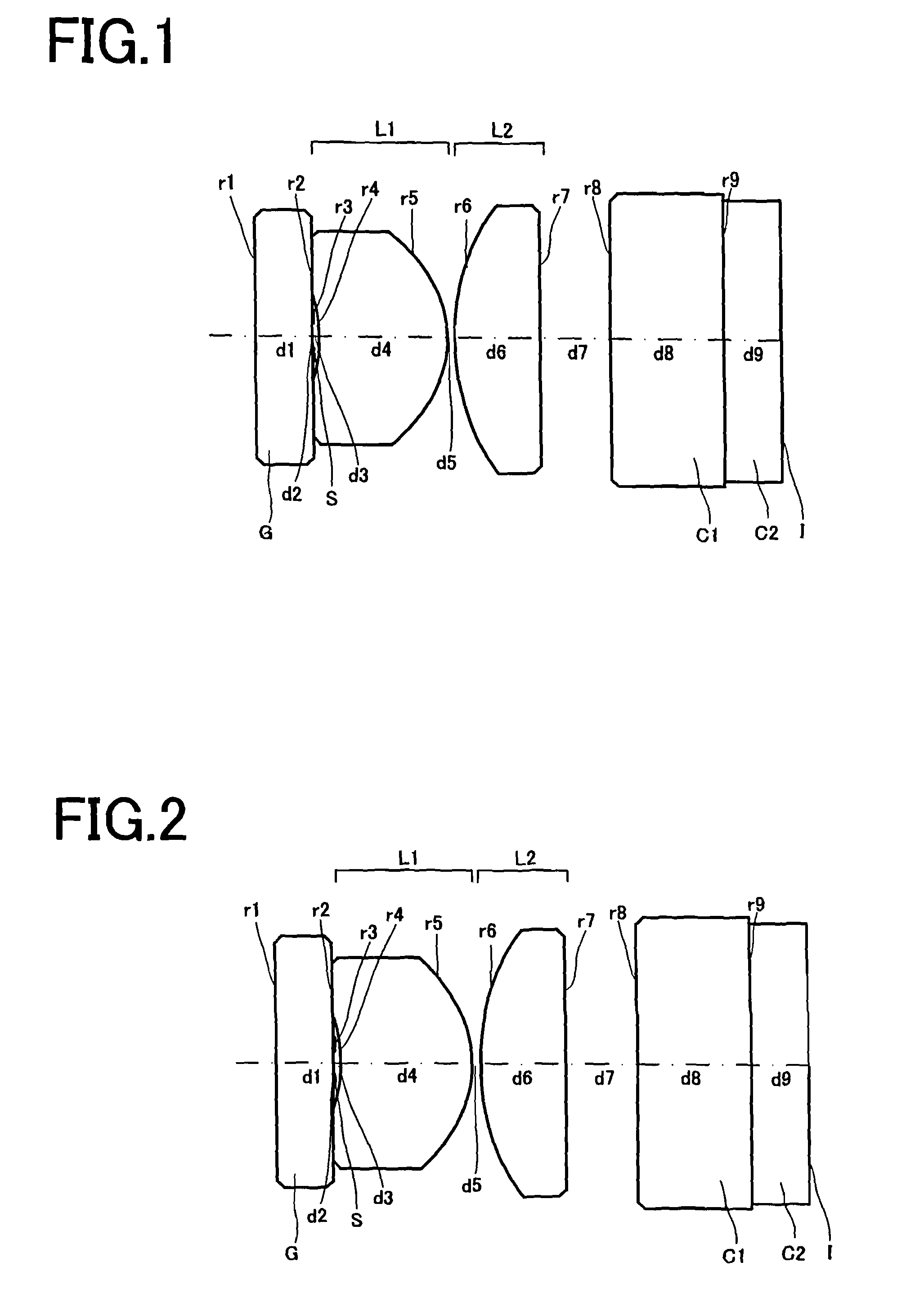
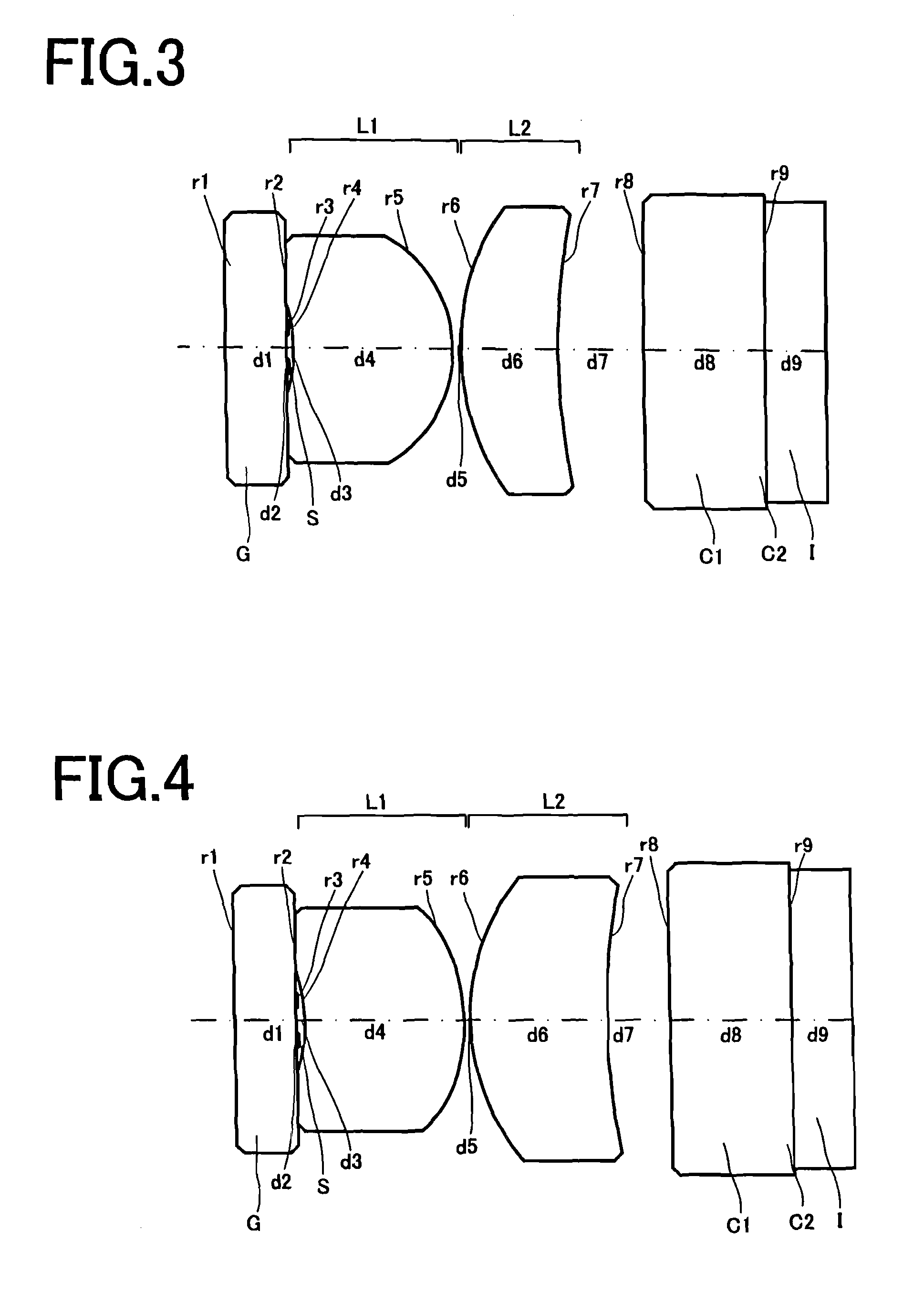
Objective optical system for endoscopes
an optical system and endoscope technology, applied in the field of endoscope objects, can solve the problems of optical systems, still less compatible with ccds having a lot more pixels, and 4 have not had an angle of view, and achieve the effect of small format and high performan
- Summary
- Abstract
- Description
- Claims
- Application Information
AI Technical Summary
Benefits of technology
Problems solved by technology
Method used
Image

Examples
numerical example 1
[0079]
Unit mmFocal Length 1.181Surface DataSurface No.rdneνdObject Point∞11.90001∞0.40001.8881540.762 (Stop)∞0.01003∞0.05004−1.10000.90001.7323454.685−0.90000.050061.65000.60001.5196575.007∞0.50008∞0.80001.5182564.149∞0.40001.6137950.20Image Plane
numerical example 2
[0080]
Unit mmFocal Length 1.182Surface DataSurface No.rdneνdObject Point∞11.90001∞0.40001.8881540.762 (Stop)∞0.01003∞0.05004−1.15000.92001.7762149.605−0.95000.050061.65000.60001.5196575.007∞0.50008∞0.80001.5182564.149∞0.40001.6137950.20Image Plane
numerical example 3
[0081]
Unit mmFocal Length 1.206Surface DataSurface No.rdneνdObject Point∞11.9000 1∞0.40001.8881540.76 2 (Stop)∞0.0100 3∞0.0500 4−1.05001.05001.6997955.53 5−0.85000.0500 61.65000.65001.5182564.14 75.00000.5600 8∞0.80001.5182564.1410∞0.40001.6137950.20Image Plane
PUM
 Abstract
Description
Claims
Application Information