
Authentication method and system

a technology of authentication method and system, applied in the field of object authentication and counterfeit detection, can solve the problems of difficult reprography, color balance and halftone shapes are extremely difficult to reproduce reprographically, and cannot be readily photocopied

Inactive Publication Date: 2010-08-10
COPILOT VENTURES FUND III
View PDF26 Cites 162 Cited by
  • Summary
  • Abstract
  • Description
  • Claims
  • Application Information

AI Technical Summary

Benefits of technology

This approach significantly enhances the security of authentication by making it difficult for counterfeiters to replicate the fiber patterns and their properties, ensuring high reliability in verifying the authenticity of objects.

Problems solved by technology

Thus, the technique relies on information which can be readily printed but not readily photocopied.
The serpentines printed in full color, with the correct color balance and halftone shapes are extremely difficult to reproduce reprographically.
The narrow, diagonally extending, unfilled areas in halftone cells representing the darker tones are especially difficult to reproduce faithfully because ordinary copying tends to cause near neighboring shapes to blur together, thereby degrading (if not obliterating) the shape information and clues that aid in determining cell direction.
This requires access to a printer that can print serpentines, an unlikely prospect for the casual counterfeiter.
This is not an absolute safeguard against counterfeiting, but it is a significant hindrance to those who may attempt to pass off xerographic copies or other conveniently produced copies as original documents.
The feature that gives serpentines a large dynamic range also makes them difficult to copy.
As the hyperbolas asymptotically approach the limiting diagonal of the halftone cell, the small region of white is extremely difficult to copy without loss of contrast.
The resulting “waffle” appearance of the halftone screen conveniently lacks directionality.
The availability of so many non-deterministic variables makes counterfeiting difficult.
In fact, it is not believed that any methods presently exist for copying fiber placement within a substrate.
The signature of every item will be different making it more difficult to reverse engineer.
Furthermore, processing of the paper (calendaring) further alters this image comparison.
The particular fluorescent agent used may be kept secret and dyes which fluoresce in non-visible regions of the electromagnetic spectrum may be employed, so copying this feature may be difficult.
One challenge to this technique is the logistics of communicating the secret key to the intended recipient without other parties gaining knowledge of the key.
With stronger encryption comes greater system complexity and longer processing durations to both encrypt and decrypt.
Another encoding scheme uses a DES-type encryption system, which does not allow decoding of the message by the public, but only by authorized persons in possession of the codes.
However, all the above methods proposed for digital watermarking generally detect modifications by means of an external signature, i.e., no metric that measures the fidelity of the original digital data is used.
Consequently, there exists no ability to measure in any detail the extent of the changes made or to estimate the precision of the received data.
Each of these increasingly complex codes is, in turn, more difficult to read and decipher.
Thus, a pattern may be provided which can be analyzed, but for which techniques for copying are generally unavailable.
By reducing the pseudorandom signal levels and modulating the pseudorandom signal on the actual noise, it becomes more difficult to duplicate the markings, and more difficult to detect the code without a priori knowledge of the encoding scheme.
In this case, the information in the database records should unambiguously authenticate or fail to authenticate the object.

Method used


Image

  • Authentication method and system
  • Authentication method and system
  • Authentication method and system

Examples


Embodiment Construction

[0245]The detailed preferred embodiments of the invention will now be described with respect to the drawings. Like features of the drawings are indicated with the same reference numerals.

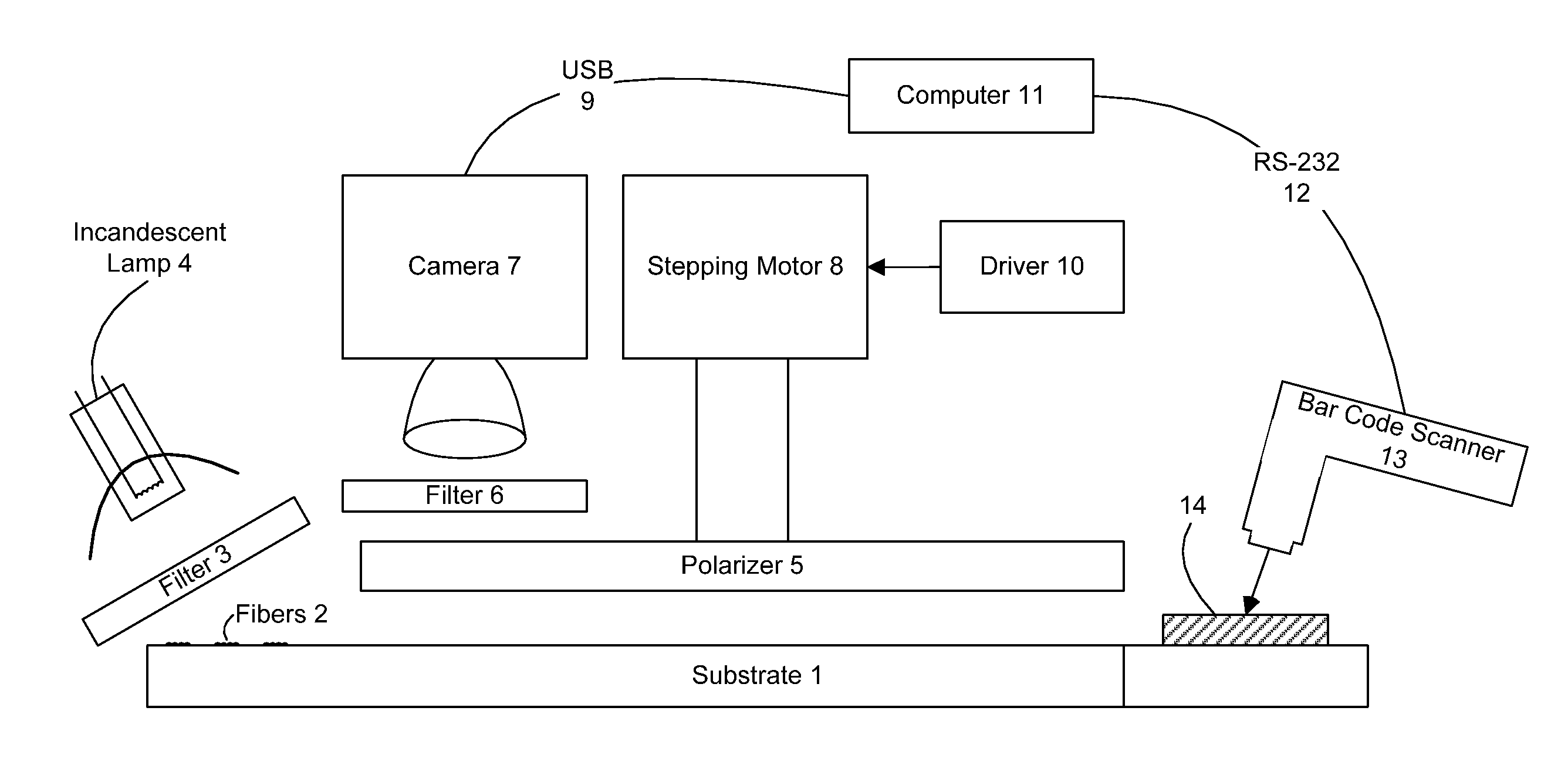
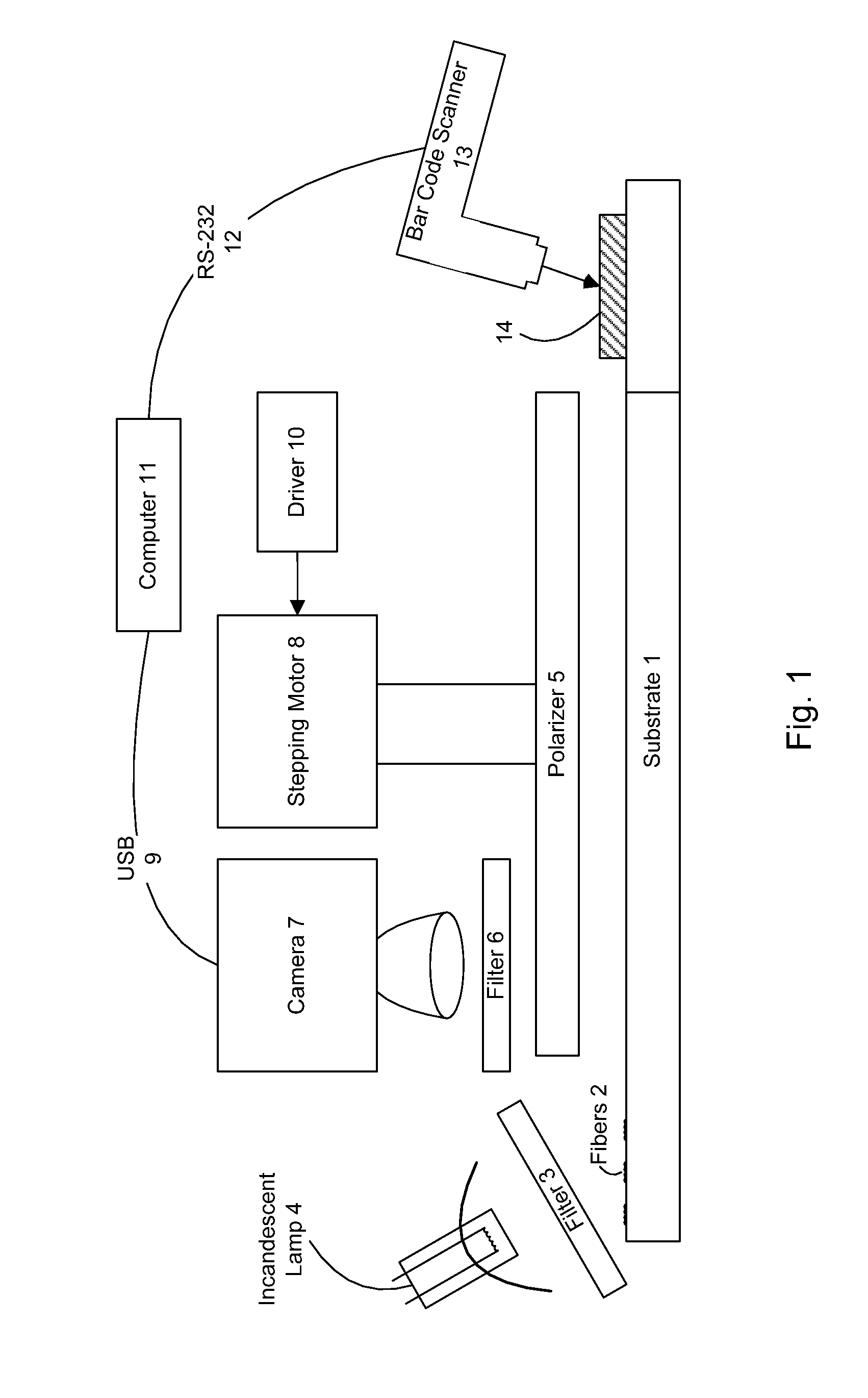
[0246]In FIG. 1, a substrate 1 with dichroic fibers 2 located on it is subject to a filter 3 of an incandescent lamp 4. A polarizer 5 is beneath a filter 6 underneath a camera 7 and this camera 7 via a Universal Serial Bus (USB) 9 is connected to a computer 11 which is in turn connected to a bar code scanner 13 via a RS-232 standard serial port 12. The bar code scanner 13 scans the bar code 14 on the substrate 1 and completes the authentication procedure with the aid of the computer 11.

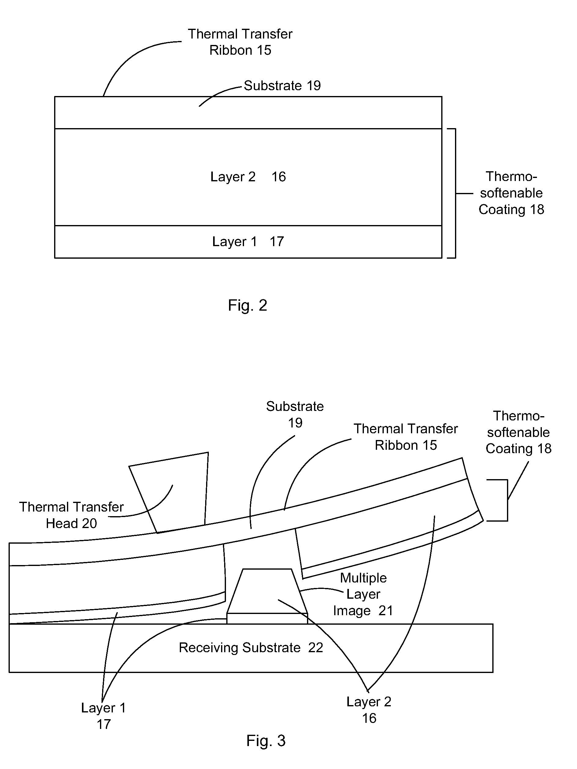
[0247]FIG. 2 shows a thermal transfer ribbon 15 comprising a substrate 19, and positioned on the substrate 19 is a thermosoftenable coating 18 which comprises a layer 16 and a layer 17. layer 17 comprises a sensible material, e.g. binder compounds. Layer 16 is crystalline, and has a melting temperature above the print...


PUM


Abstract

The present invention provides a method and apparatus for the production and labeling of objects in a manner suitable for the prevention and detection of counterfeiting. Thus, the system incorporates a variety of features that make unauthorized reproduction difficult. In addition, the present invention provides an efficient means for the production of labels and verification of authenticity, whereby a recording apparatus which includes a recording medium, having anisotrophic optical domains, along with a means for transferring a portion of the recording medium to a carrier, wherein a bulk portion of the recording medium has macroscopically detectable anisotrophic optical properties and the detecting apparatus thereon.

Description

RELATED APPLICATIONS[0001]The preset application is a Divisional of U.S. patent Ser. No. 09 / 577,959, filed May 24, 2000, now U.S. Pat. No. 7,162,035, which is expressly incorporated herein by reference it its entirety.FIELD OF THE INVENTION[0002]The present invention relates to the field of object authentication and counterfeit detection, and more particularly to improved hardware devices and methods of use thereof.BACKGROUND OF THE INVENTION[0003]The issues of authentication and counterfeit deterrence can be important in many contexts. Bills of currency, stock and bond certificates, credit cards, passports, bills of lading, as well as many other legal documents (e.g., deeds, wills, etc.) all must be reliably authentic to be useful. Authentication and avoidance of counterfeiting can also be important in many less obvious contexts. For example, improved verification / counterfeiting prevention mechanisms would be very useful in, for example, verifying the contents of shipping container...

Claims


Application Information

Patent Timeline
Patent Type & Authority Patents(United States)
IPC IPC(8): G09C5/00
CPCG06K19/086G09C5/00H04L9/3236H04L9/3247H04L2209/805H04L2209/56H04L2209/608G06Q30/0185G06K7/12G06K7/1404G06F21/602H04L9/3242H04L2209/24
Inventor DURST, DAVID I.KAISH, NORMANFRASER, JAYHOFFBERG, MICHAELRODRICKS, BRIAN
Owner COPILOT VENTURES FUND III
Learn More