Tissue scanner

a tissue scanner and scanner technology, applied in the field of tissue scanners, can solve the problems of increasing limitations in spatial resolution and fluorescence imaging in intact animals

Inactive Publication Date: 2010-08-10
OPTOSONICS
View PDF4 Cites 10 Cited by
  • Summary
  • Abstract
  • Description
  • Claims
  • Application Information

AI Technical Summary

Benefits of technology

[0012]Thermoacoustic imaging using fluorescent dye markers may be used in combination with thermoacoustic imaging, and / or conventional ultrasound imaging, to produce overlaid enhanced images. Specifically, excitation frequencies both inside and outside the frequency band of fluorescence of the dye marker may be used to develop thermoacoustic images using and independent of the dye marker fluorescence.

Problems solved by technology

However, the deleterious effects of optical scattering compromises fluorescence imaging in intact animals, and limits spatial resolution increasingly with the depth of the site of markers within soft tissue.

Method used


Image

  • Tissue scanner
  • Tissue scanner
  • Tissue scanner

Examples


Embodiment Construction

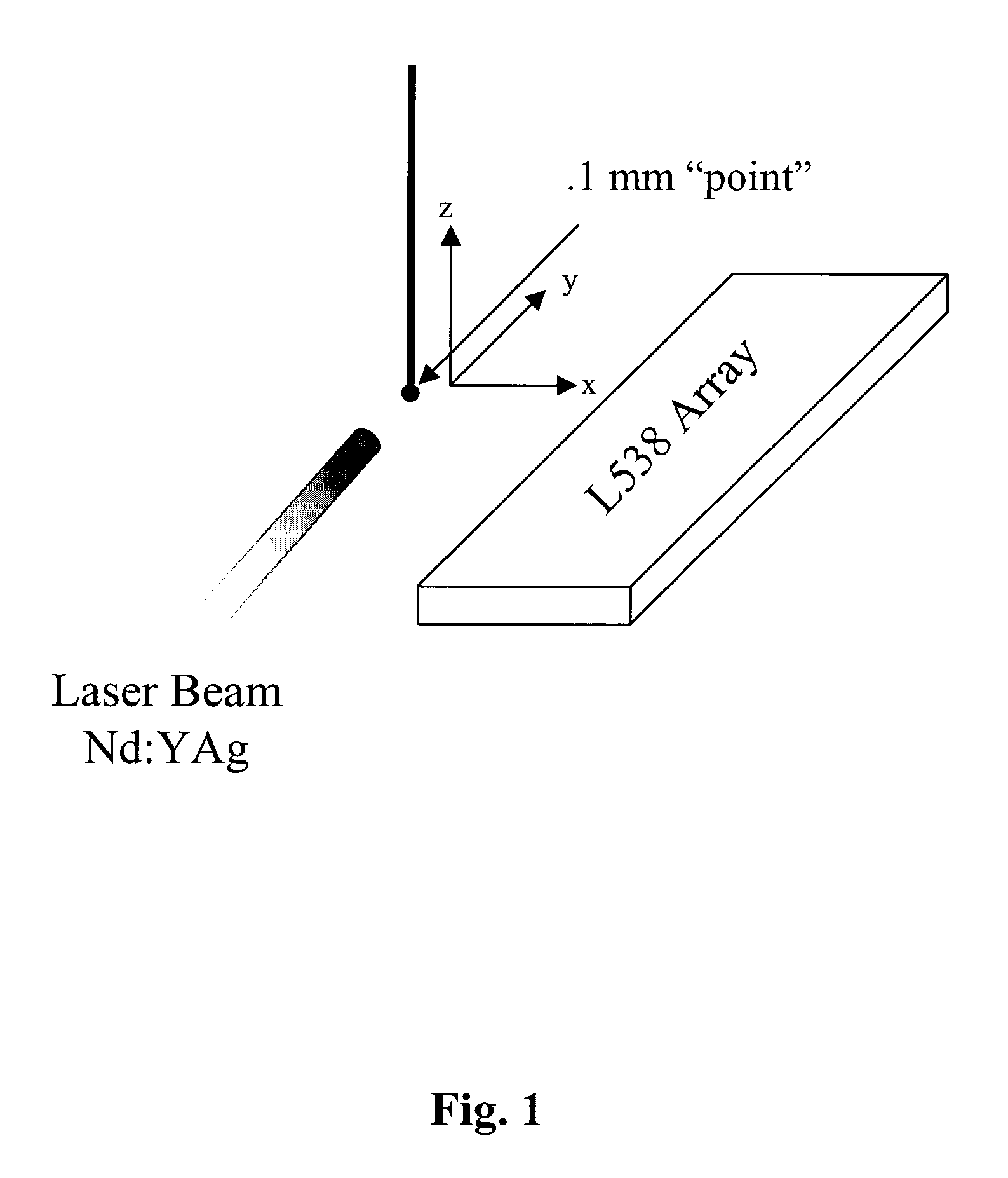
[0024]FIG. 1 illustrates a commercial, linear array 8 arranged for testing as a photoacoustic detector (specifically, Model No. L538, available from Acuson, Mountain View, Calif.). This array comprises 128 elements spanning 38 mm. The elements have a nominal central frequency of 5 MHz, and are spaced 0.3 mm apart. Each element is nominally 6-mm high, with a thin acoustic lens that produced a geometric focus approximately 15 mm in front of the array.

[0025]The slice-width profile of this array was measured normal to the imaging plane, from the axial response of the array to a photoacoustic “point” source 9, as illustrated in FIG. 1. The thermoacoustic “point” was fabricated by painting a small “dot” of black paint on the end of a 0.10-mm diameter, polyethylene thread. The thread was mounted on a two-axis positioner and pulsed with light from a Nd:YAg laser, which produced an approximately 6 ns pulse of 1064 nm infrared radiation. The position of the point source was slowly varied with...


PUM


Abstract

A three-dimensional thermoacoustic imaging system uses dye markers. Thermoacoustic signals are produced by the dye markers when light from an external source is absorbed by the dye. Thermoacoustic images with and without dye stimulation may be generated using excitation frequencies both inside and outside the frequency band of fluorescence of the dye marker, and these may be combined, and/or combined with conventional ultrasound images for image enhancement. An apparatus for carrying out this method on mice, uses a commercially available array of transducers positioned opposite to the body of the mouse, which is immersed in a coupling media. A source of illumination such as a laser directs light to the mouse through the coupling media, and resulting acoustic waves are captured by the array and reconstructed to form an image.

Description

[0001]This application claims priority from U.S. Provisional patent application No. 60 / 414,000, filed Sep. 26, 2002, and application Ser. No. 09 / 884,766 filed Jun. 19, 2001, now U.S. Pat. No. 6,490,470, a divisional of which was filed Nov. 15, 2002, as application Ser. No. 10 / 295,468, which issued as U.S. Pat. No. 6,633,774 on Oct. 15, 2003. This application is related to application Ser. No. 09 / 243,004 filed Feb. 2, 1999, entitled THERMOACOUSTIC COMPUTED TOMOGRAPHY SCANNER, now U.S. Pat. No. 6,216,025, which is a divisional application of Ser. No. 09 / 076,385 filed May 12, 1998, now U.S. Pat. No. 6,104,942, and application Ser. No. 09 / 076,968 filed May 13, 1998, now U.S. Pat. No. 6,102,857, which is a divisional of Patent Cooperation Treaty application designating the Ser. No. 97 / 17832, filed Oct. 1, 1997, which is a continuation of application Ser. No. 08 / 719,736, filed Oct. 4, 1996, now U.S. Pat. No. 5,713,356, issued Feb. 3, 1998, all of the foregoing being filed in the name of t...

Claims


Application Information

Patent Timeline
Patent Type & Authority Patents(United States)
IPC IPC(8): A61B5/05A61B5/00
CPCA61B5/0059A61B5/0095A61B5/0507
Inventor KRUGER, ROBERT A.
Owner OPTOSONICS
Why Eureka
Try Eureka