Method of transforming thermal energy

a technology of thermal energy and thermal energy, applied in the direction of steam engine plants, hot gas positive displacement engine plants, machines/engines, etc., can solve the problems of inability to complete and convenient mapping of temperature differences to liquid boiling points, engine efficiency is rather inconvenient, and the mapping of temperature differences is not complete and convenien

Active Publication Date: 2010-08-17
TICE NEIL
View PDF21 Cites 13 Cited by
  • Summary
  • Abstract
  • Description
  • Claims
  • Application Information

AI Technical Summary

Problems solved by technology

If, however, one wishes to harvest a temperature difference between two volumes, both of which are at a temperature below the boiling point of water, this method is unavailable.
Although there are liquids, other than water that have different boiling points, there is far from a complete and convenient mapping of temperature differences to liquid boiling points.
Additionally, although thermal engines employing a solid phase change material, such as Nitinol, have been designed, these engines tend to be rather inefficient and do not take advantage of the full phase change expansion that Nitinol undergoes.
Many of the existing designs do not fully insulate the heat source from the heat sink and therefore do not efficiently use the available heat.

Method used


Image

  • Method of transforming thermal energy
  • Method of transforming thermal energy
  • Method of transforming thermal energy

Examples


Embodiment Construction

)

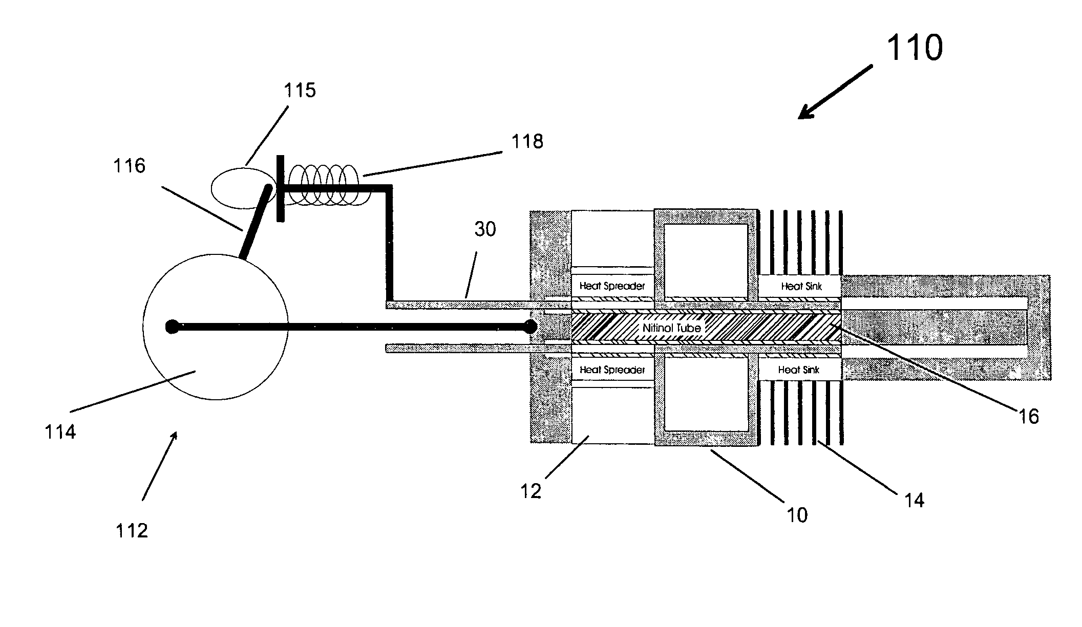
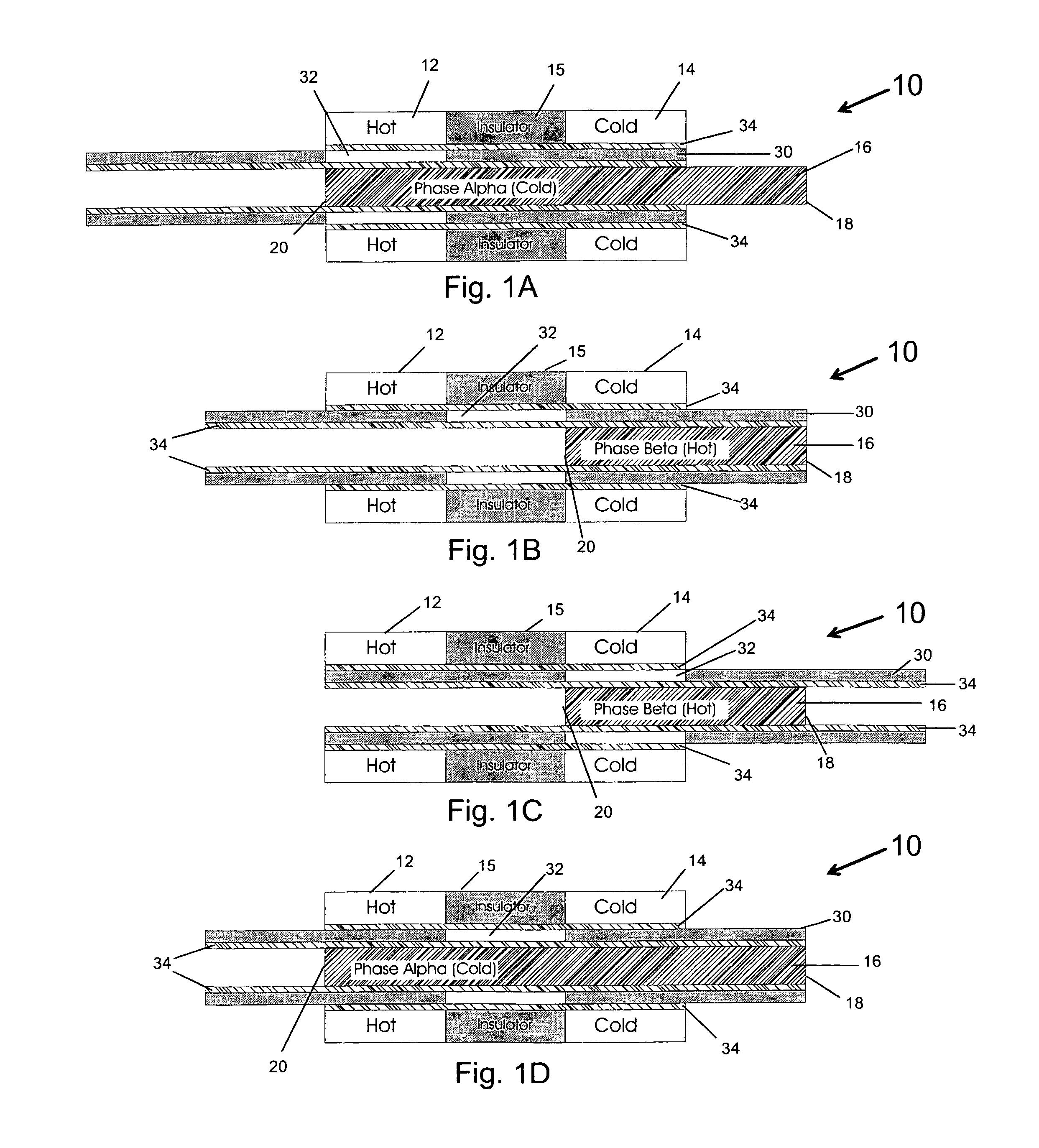
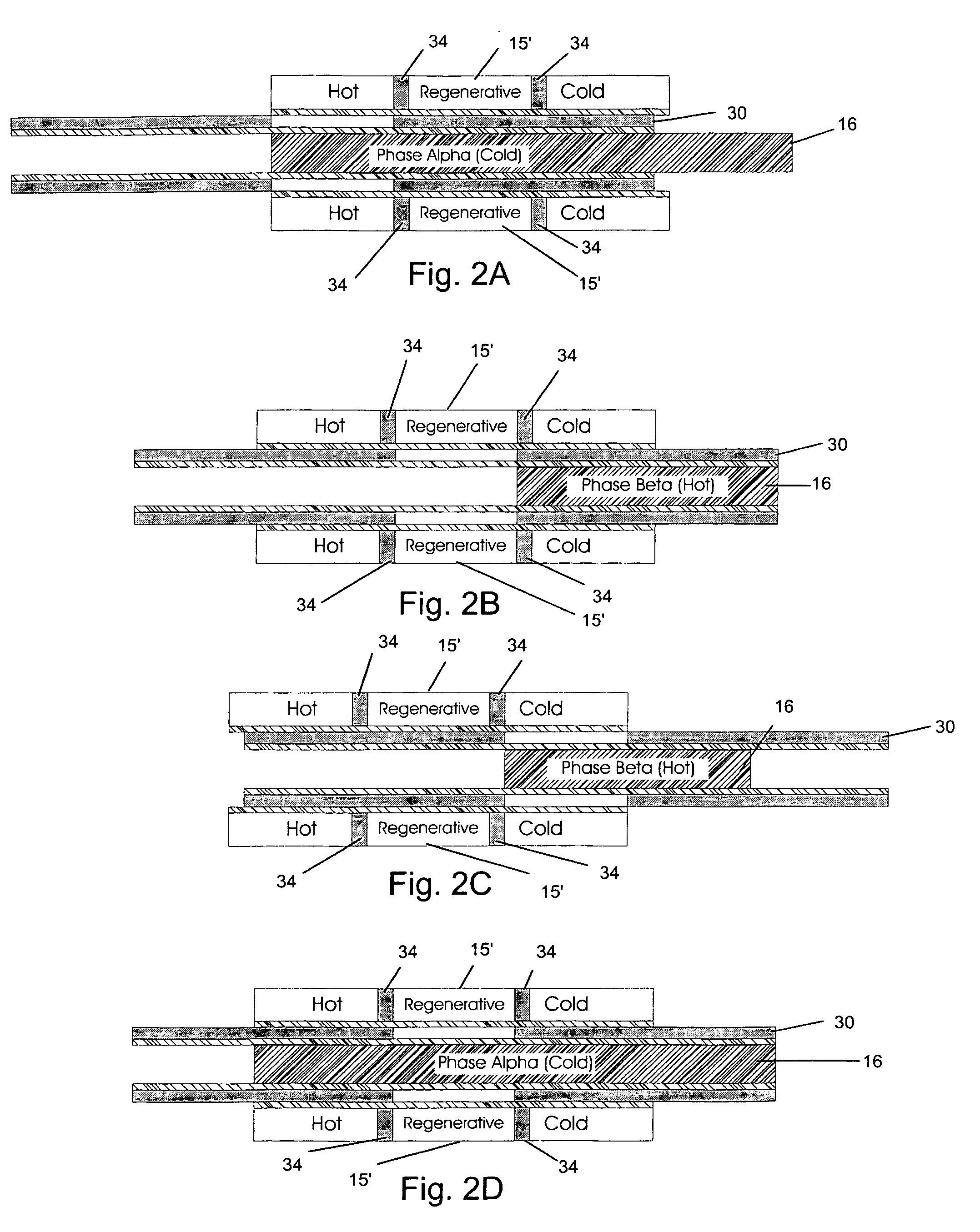
[0014]FIGS. 1A-1D, is a simplified system illustration for showing the theory of operation of a preferred embodiment of the present invention. This embodiment incorporates an assembly 10 for creating kinetic energy from a juxtaposed warm region 12 and cold region 14, separated by an insulator 15. A tube of shape memory material 16, such as Nitinol is set into assembly 10 so that a first end 18 is fixed in position and a second end 20 is free to move as a result of phase change expansion and contraction. Nitinol, an alloy of nickel and titanium that is well documented, expands when cooled through the phase change transition point, and contracts when warmed through this transition.

[0015]A tube 30 of insulating material partially surrounds article 16 and defines a thermal window 32, which is thermally conductive. Layers of thermally conductive lubricant 34 help tube 30 to be slid back and forth.

[0016]In a first stage, shown in FIG. 1A, tube 16 is in its cold and elongated phase. It is...


PUM


Abstract

A method of generating motion from a cool region that is proximal to a warm region, the cool region and the warm region defining a temperature range. The method uses an article of phase change material having a warm-to-cold phase transition and a cold-to-warm phase transition, both within the temperature range. This article is exposed to the cool region, thereby causing the phase change material to change size. When the warm-to-cold phase transition is substantially complete, this is detected. In response to this detection the article is exposed to the warm region, thereby causing the phase change material to change size. When this transition is substantially complete, the cycle is restarted with exposure to the cool region.

Description

BACKGROUND OF THE INVENTION[0001]Many ideas for improvements in the world's energy usage focus on increasing the efficiency of existing types of engines. Most heat engines are limited in their efficiency by the theoretical efficiency of the Carnot cycle, which requires an increase in operating temperature in order to increase operating efficiency. Rather than the focus on efficiency, it may be desirable to harvest energy at a reasonable efficiency from relatively slight differences in temperature between two volumes. Currently, electric energy is typically produced by boiling water and using the steam generated to drive a turbine. This works very well if one creates a first volume with a temperature above the boiling point of water and a second volume with a temperature below the boiling point of water.[0002]If, however, one wishes to harvest a temperature difference between two volumes, both of which are at a temperature below the boiling point of water, this method is unavailable....

Claims


Application Information

Patent Timeline
IPC IPC(8): F01B29/10F02G1/04
CPCF03G7/00
Inventor TICE, NEIL
Owner TICE NEIL
Why Eureka
Try Eureka