
Multivalve hypervelocity launcher (MHL)

a hypervelocity launcher and multi-valve technology, applied in the direction of weapons, white arms/cold weapons, weapons, etc., can solve the problem of short distance of travel of propelling gas to the base of the projectile, and achieve the effect of reducing the cos

Inactive Publication Date: 2010-08-17
MCDERMOTT PATRICK P
View PDF17 Cites 62 Cited by
  • Summary
  • Abstract
  • Description
  • Claims
  • Application Information

AI Technical Summary

Benefits of technology

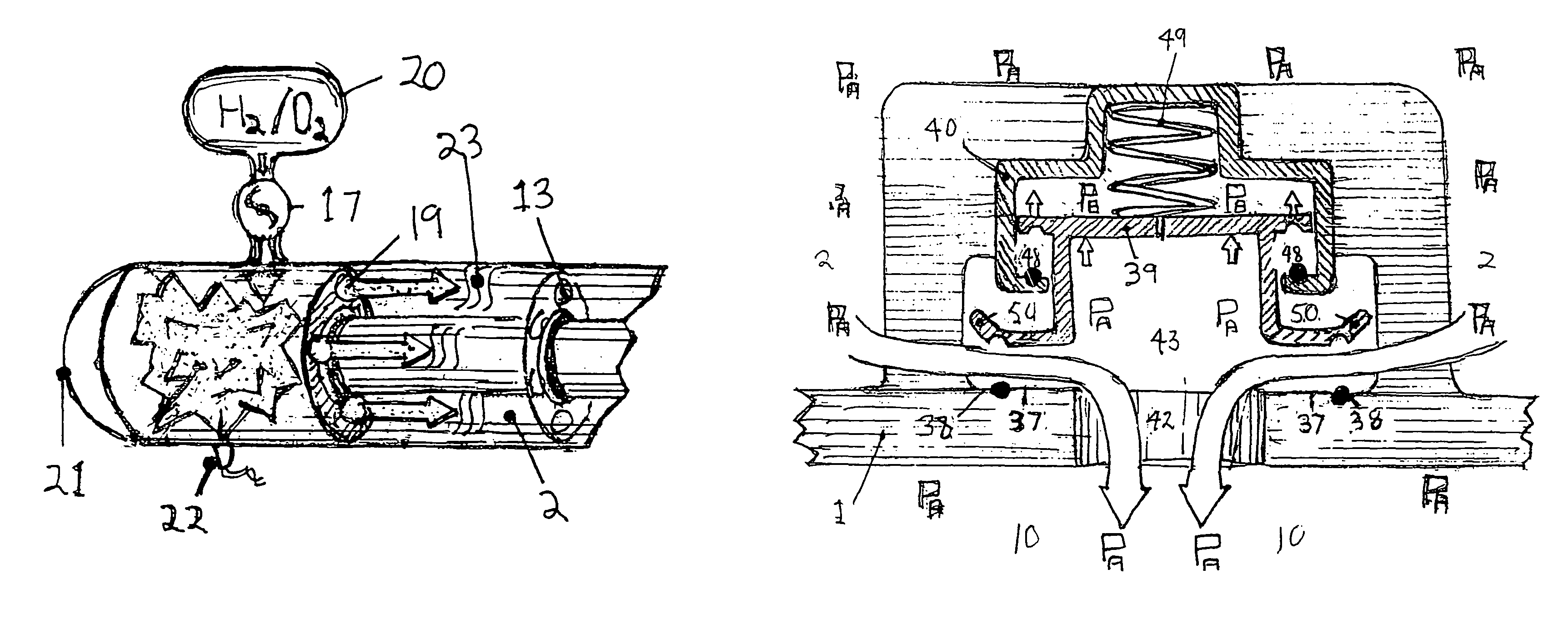
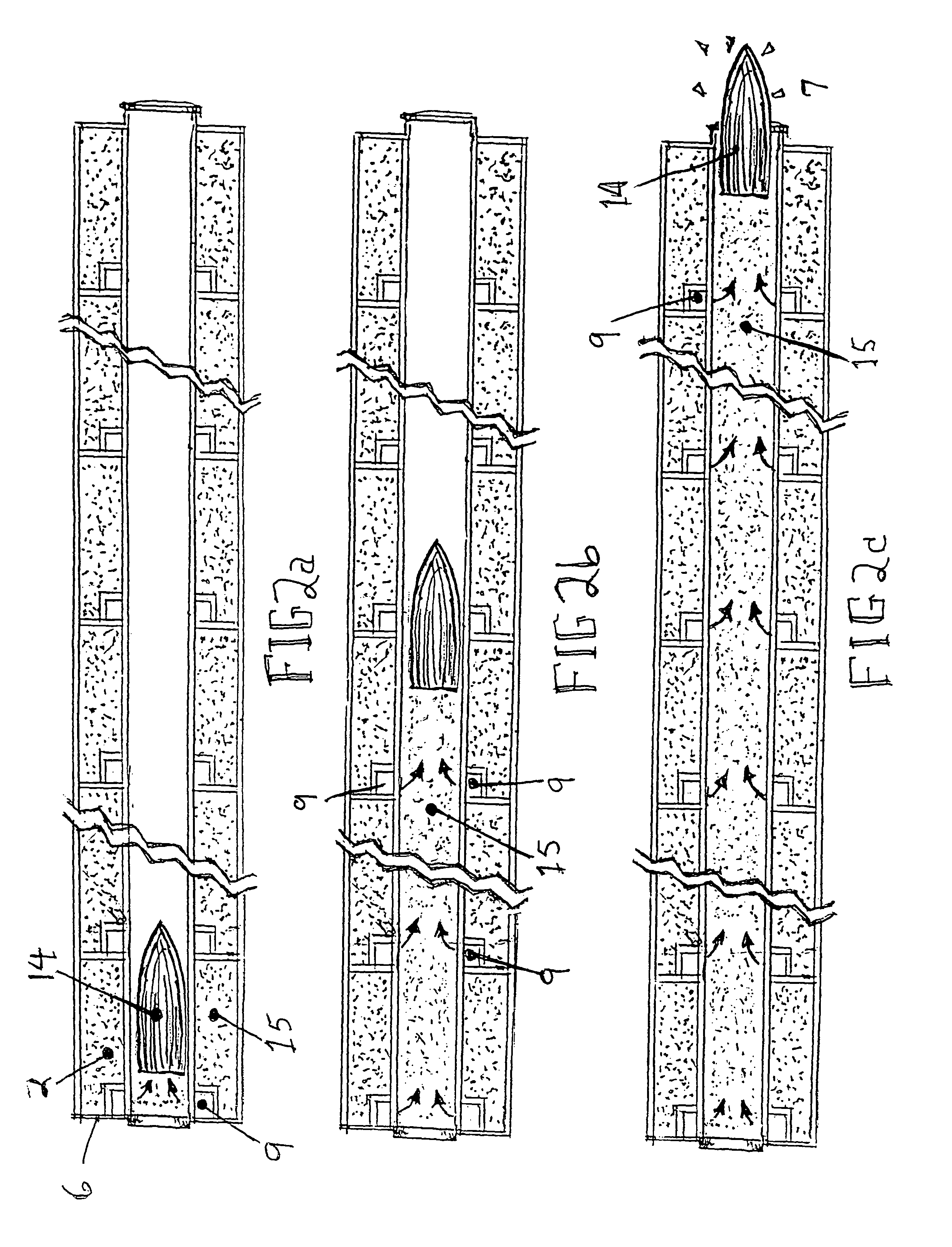
[0015]The new multivalve hypervelocity launcher (MHL) utilizes the same basic principal of sequential introduction of high-pressure gas behind the projectile, but with a different design architecture that is more efficient, potentially much lower cost, transportable, and suitable for launching larger projectiles. The MHL system contains attributes of some of the above-mentioned systems, such as the storage of high-pressure light gas, combustion of hydrogen / oxygen to produce the high pressure gas, venting of the gas at intervals along the barrel, and the use of base-bleed projects. But the MHL differs significantly in how the compressed gas / or ignition products are stored and injected into the barrel behind the projectile at the multiple ports. The MHL launcher invention overcomes many of the limitations described above, by injecting high-pressure gas in a continuous manner through many ports behind the projectile all along the path of its travel down the barrel. The projectile experiences a more constant, albeit higher, accelerating force throughout the length of the barrel, because the pressure head behind the projectile is constantly refreshed by the opening of valves sequentially along the barrel, and the release of high pressure gas behind and at the base of the projectile, as the projectile traverses the barrel. This avoids the high-G pressure spikes normally associated with conventional chemical guns, and avoids the phenomenon of the projectile being limited by the velocity limits of the shock wave of the expanding gas.
[0016]The MHL system utilizes a soft launch technique that simplifies the construction of the payload and opens up a spectrum of payloads that can be accommodated by the launcher. The payload projectile, its components, and electronics need not be hardened against the high-G pressure spikes. 10,000 g constant force replaces 50,000 g peaks found in chemical guns. This gives flexibility in the use of the materials and structures that can sustain a constant, but lower G level during the launch process.

Problems solved by technology

Thus, the distance of travel of the propelling gas to the base of the projectile is short, such that the pressure head, originally developed in the breech of the barrel is constantly replenished as the projectile travels down the barrel.

Method used


Image

  • Multivalve hypervelocity launcher (MHL)
  • Multivalve hypervelocity launcher (MHL)
  • Multivalve hypervelocity launcher (MHL)

Examples


Embodiment Construction

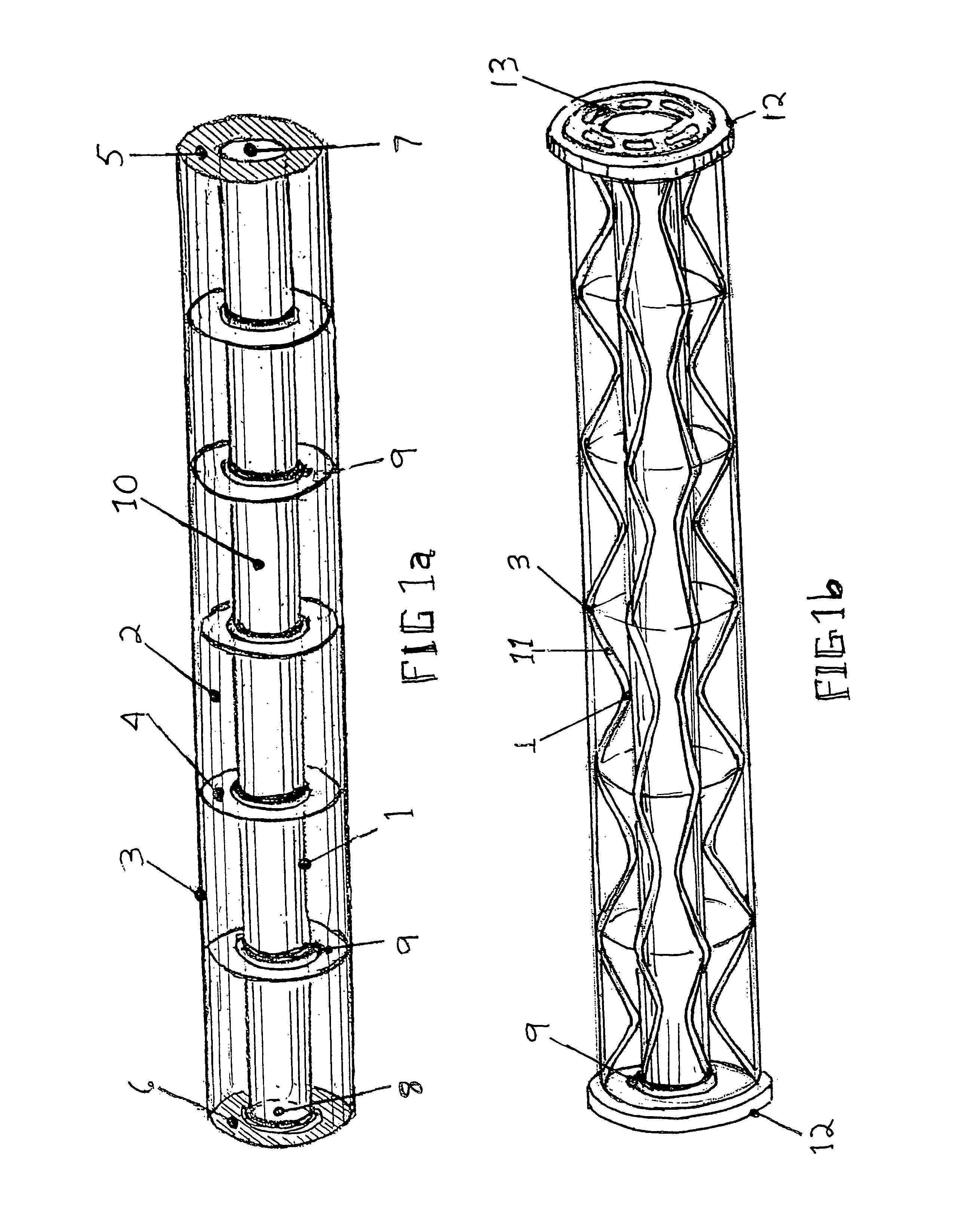
[0074]FIG. 1a shows this basic structure of the MHL system. This includes the inner barrel 1 which contains the projectile during the launch sequence; the AGC, axial gas chamber 2 formed by the IB, inner barrel 1 and the OC, outer casing 3; with internal bulkheads 4 other structures that align and connect the inner barrel and the outer casing, end closure bulkheads fore 5 and aft 6.

[0075]The muzzle end of the barrel can be closed off with a frangible cap 7 or fast acting retractable valve or cover that opens just prior to exit of the projectile and closes after exit of the projectile, to conserve the pressurized Helium or Hydrogen. At the other end is the breech assembly 8 that allows insertion of the projectile, and when closed and sealed, allows the inner barrel chamber IBC to be evacuated. Activation valves 9 shown at each internal bulkhead, when triggered, allow high-pressure gas in the AGC 2 to flow into the IBC 10 behind the projectile. FIG. 1a shows a composite of the major e...


PUM


Abstract

Launching payloads at high velocity uses high-pressure gas or combustion products for propulsion, with injection of high pressure gas at intervals along the path behind the payload projectile as it accelerates along the barrel of the launcher. An inner barrel has an interior diameter equal to the projectile diameter or sabot containing the projectile. An outer casing surrounds the inner barrel. Structures at intervals attach the outer casing and the inner barrel. An axial gas containment chamber (AGC) stores high pressure gas between the inner barrel wall, the outer casing wall, and enclosure bulkheads. Pressure-activated valves along the barrel sequentially release the high pressure gas contained in the AGC in to the barrel to create a continuously refreshed high energy pressure heads behind the projectile as it moves down the barrel. A frangible cover at the exit end of the barrel allows the barrel to be evacuated prior to launch. The launcher is rapidly recyclable. The valves close automatically after the projectile has exited the barrel, allowing a new projectile to be introduced into the breech and the AGC to be recharged with high-pressure gas.

Description

[0001]This application claims the benefit of U.S. Provisional Application No. 60 / 642,125 filed Jan. 10, 1005, which is hereby incorporated by reference in its entirety.BACKGROUND OF THE INVENTION[0002]1. Field of the Invention[0003]This invention relates to a mean for propelling payloads along a barrel utilizing compressed gas or combustion products.[0004]2. Description of Prior Art[0005]Conventional guns hurl projectiles along the gun barrel by means of chemical propellants which, when ignited in the breech, create high-pressure gases which expand behind the projectile, accelerating it along the barrel. This method, used in forms of weaponry, from cannons, to rifles and handguns, has a fundamental limitation. Once the projectile reaches a high velocity, its speed approaches a limit corresponding to the velocity of the shock wave of the expanding gas.[0006]In practice, the pressure in a gun barrel typically spikes early in the discharge of the gun so that the projectile experiences ...

Claims


Application Information

Patent Timeline
IPC IPC(8): F41A1/02
CPCF41A1/02F41A1/04F41B11/723F41A21/10F41B11/62F41A21/02
Inventor MCDERMOTT, PATRICK P.
Owner MCDERMOTT PATRICK P
Learn More