Radar system and method

a radar and system technology, applied in the field of radar systems and methods, can solve the problems of short voltage, ineffective coupling, and difficulty in concentrating low frequency radiation on targets

Active Publication Date: 2010-08-17
STATE OF ISRAEL MINIST OF AGRI & RURAL DEV AGRI RES ORG (A R O) (VOLCANI CENT)
View PDF10 Cites 35 Cited by
  • Summary
  • Abstract
  • Description
  • Claims
  • Application Information

AI Technical Summary

Benefits of technology

[0032]In one embodiment of the invention, the transmissions from the transmitting antennas are orthogonally polarized one with respect to the other, for eliminating the production of parasitic signal components at the frequency to which the receiving unit is tuned.
[0033]Preferably, the said orthogonal polarization is used for eliminating transmission of signals at the frequency of the receiving unit from any of the transmitting units.
[0036]Preferably, a multi-beam antenna is used at the receiving unit for improving the direction resolution.

Problems solved by technology

In practice, it is difficult to concentrate low frequency radiation on targets, and also the coupling is not efficient (the term “coupling” refers to the ratio between the voltage induced on a component inside the target object and between the intensity of the electromagnetic field surrounding the target object).
On the other hand, parasitic capacitance of the junctions that are part of the object, for example, PN junctions in semiconductor components within the object, metal-semiconductor junctions, or metal-oxide-metal junctions, tend to short the voltage in high frequencies.
Parasitic harmonic signals that are developed in the transmitting unit cause significant problems in distinguishing the searched objects from their surrounding.
Also, metal junctions in the antenna and the transmission lines may create odd harmonics.
These transmitted harmonic frequencies are scattered by all objects and may mask the expected scattered harmonic signals from the non-linear objects, and prevent their detection and investigation.
This is a particular problem when using antennas having strong side-lobes, that cause problems in short-range detection in any type of radar system.

Method used


Image

  • Radar system and method
  • Radar system and method
  • Radar system and method

Examples


example 1

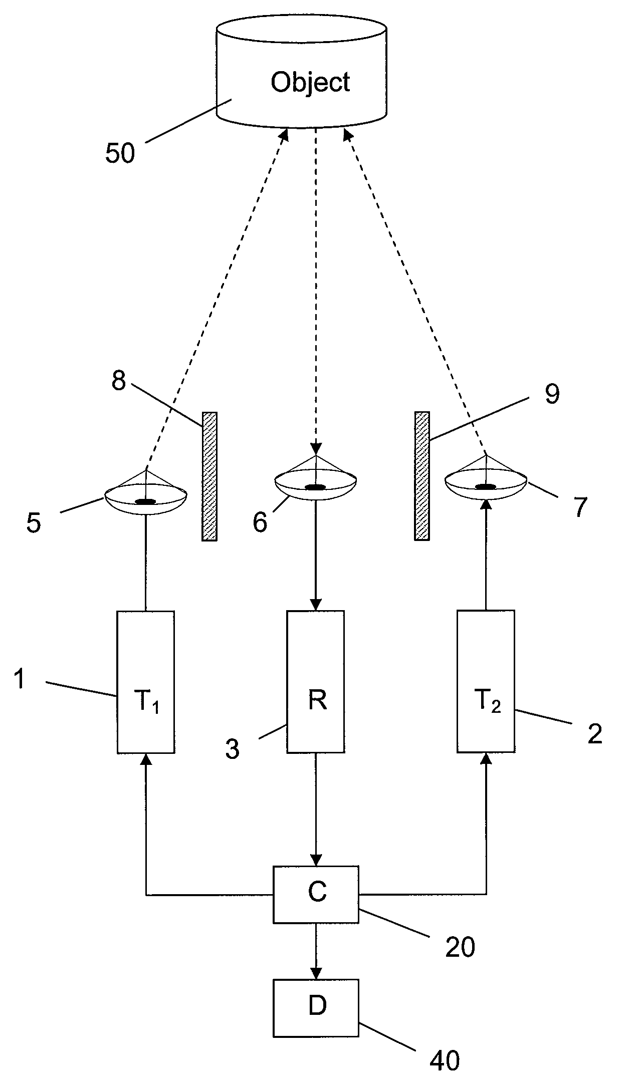
[0071]The following is an example for an efficient frequency selection that provides a system having high sensitivity to the detection of man-made objects. According to this example the transmitting frequencies are f1=2.74 GHz, f2=1.26 GHz, and the reception frequency is fr=4.0 GHz (being the sum f1+f2). Note that all frequencies in this example are rounded values to within 10 MHz. In that case the harmonics created at the transmitter 2 are in frequencies 5.48 GHz, 8.22 GHz, 10.96 GHz, . . . etc., and the harmonics created at the transmitter 4 are in the frequencies 2.52 GHz, 3.78 GHz, 5.04 GHz, . . . etc. It has been demonstrated that in this example the receiving frequency, when properly selected, is remote enough from each of the transmitting frequencies, and / or from any of their harmonics. Therefore, the sensitivity and the ability of the system to distinguish man-made target from their surroundings are improved.

[0072]In one preferred embodiment of the invention, the system of t...

example 2

[0082]The following example compares two radar systems radiating same pulse energy.

[0083]Radar system a, similar to the system of WO 02 / 39140 (Jablonsky et. al., also mentioned in the “Background of the Invention” section) emits typical pulse width τa=0.3 ms with typical pulse peak power Pa=0.3 W.

[0084]Radar system b, having transmitted pulse width as in the present application, typically τb=10 ns, and the same pulse energy as in Radar system a: pulse peak power Pb=9 kW.

[0085]Note that if both use same pulse repetition frequency (PRF), they also emit the same average power. For example a>=b>=0.1 W for PRF=1111 pps.

[0086]The re-radiated n-harmonic power from a non-linear object as discussed in the present application is proportional to the n-power of the flux (power density) impinging on the object. That straight forward rule applies, at a certain domain, to any non-linear phenomena of order n. In conventional (linear) radars, however, the re-radiated (or reflected) power is proporti...

example 3

[0094]Following the comparison between the two harmonic radars of EXAMPLE 2, we now analyze the implications of extending the range from 10 m to about 500 m. For the analysis to be meaningful, it is assumed that both systems use the same repetition rate, integration method, antennas, same receiver, and both look for the same object.

[0095]Radar system a, similar to WO 02 / 39140 (Jablonsky et. al. also mentioned above and in the “Background of the Invention” section) emits typical pulse width τa=0.3 ms with typical pulse peak power Pa=0.3 W.

[0096]Radar system b, having transmitted pulse width as in the present application, typically τb=10 ns, and the same pulse energy as in Radar system a: pulse peak power Pb=9 kW.

[0097]Radar system a, has a typical detection range of 10 m and we ask what is the required pulse energy or average power to extend the detection range to 500 m.

[0098]Re-writing the SNR relation of EXAMPLE 2:

SNR∝τ×(PG / 4πR2)n×Gr(λr / 4πR)2∝E×Pn−1R−(2n+2); E≡τ×P

where R is the ra...


PUM


Abstract

The invention relates to a radar system which comprises: (a) at least two transmitting units for simultaneously, and in synchronization transmitting electromagnetic radiation in distinct frequencies f1, f2, f3 . . . towards a space of interest; and (b) at least one receiving unit tuned to a frequency of nf1+mf2+qf3 . . . , wherein n, m, q . . . being integers not equal to zero, for receiving a non-linear response of said radiation from objects located within the said space of interest, and wherein the system is characterized in that said transmitted pulses are narrow pulses having duration in the range of between about 1 nanoseconds and about 100 nanoseconds.

Description

CLAIM OF PRIORITY[0001]This application claims priority as a continuation-in-part of U.S. patent application Ser. No. 11 / 179,763, filed on Jul. 12, 2005.FIELD OF THE INVENTION[0002]The invention generally relates to a method and system for detecting and locating man-made objects by means of a “harmonic radar” utilizing the objects non-linear response to incident electromagnetic waves.BACKGROUND OF THE INVENTION[0003]Radar systems are widely used for detecting and locating objects. Radar systems usually operate in the UHF (Ultra-High-Frequency) or microwave part of the RF (Radio-Frequency) spectrum, and are used to determine the position and / or movement of an object. There have been developed various types of radar systems, for different purposes and applications.[0004]Any radar system can locate a target by finding its direction and range. The range to an object is determined by calculating the delay between a pulse transmitted by the system, and the consequential receipt of the ref...

Claims


Application Information

Patent Timeline
Patent Type & Authority Patents(United States)
IPC IPC(8): G01S7/292G01S13/00
CPCG01S7/282G01S7/285G01S13/106G01S7/024
Inventor SCHNITZER, ITZHAKROSENBERG, AVNERDEUTSCH, ALON
Owner STATE OF ISRAEL MINIST OF AGRI & RURAL DEV AGRI RES ORG (A R O) (VOLCANI CENT)
Why Eureka
Try Eureka