Seal chamber conditioning valve for a rotodynamic pump

a technology of rotodynamic pump and sealing chamber, which is applied in the direction of machines/engines, engine starters, liquid fuel engines, etc., can solve the problems of high potential for dry running at the seal face, dry running condition, and mechanical seal wear, so as to improve the preservation and maintenance of mechanical seals

Inactive Publication Date: 2010-08-24
WEIR SLURRY GRP INC
View PDF11 Cites 4 Cited by
  • Summary
  • Abstract
  • Description
  • Claims
  • Application Information

AI Technical Summary

Benefits of technology

[0011]In accordance with the present invention, a valve mechanism, positioned in the seal chamber of a rotodynamic pump, is structured to provide selective modification of the contents or condition of the seal chamber to assure proper operation and condition of the mechanical seal at all times, thereby improving the seal life of the pump. While the seal chamber conditioning valve mechanism of the present invention is described for use in a centrifugal pump of the slurry type, the valve mechanism may be adapted for use in other types of equipment that use mechanical seals. including for example, clear liquid pumps and turbines.
[0014]The valve is generally conically shaped, thereby effecting a conical-like spray of fluid into the seal chamber. Consequently, the positioning of the valve mechanism in the seal chamber and the conical-like spray pattern produced by the valve enables fluid to be delivered about the surfaces of the seal chamber to flush down and remove accumulated solids from the surfaces of the seal chamber. The valve mechanism is also directed to spray in the direction of the seal face of the mechanical seal to provide cooling and lubrication of the seal face. The valve mechanism is also positioned in the seal chamber to enable the conical-like spray of the valve to break up large air bubbles and to disperse the toroidally-shaped air bubble mass that may form about the pump shaft at high air concentrations. The dissipation of air bubbles from the area causes the seal chamber environment to improve by modifying the seal chamber condition to a more homogeneous mixture of fluid and solids.
[0016]When an external source of fluid is provided, via a fluid conduit, to the valve mechanism, the configuration of the valve assures that the valve will center properly on the valve seat and will close properly. Application of pressurized fluid to the housing provides a flushing of the valve housing to eliminate the accumulation of solids in the valve housing.
[0017]The spring-loaded construction of the valve, in an exemplary embodiment of the invention, enables the valve to close if excessive pressurization of the valve occurs. That is, the conical spring that seats the valve will close upon itself if the amount of pressure exerted on the valve exceeds a selected load on the conical spring. Automatic closure of the valve mechanism prevents excessive flow of pressurized fluid and prevents excessively high pressure flushing fluid from reaching the seal chamber and seal face, which would introduce undesirable turbulence into the seal chamber. The conical spring about the valve has an added advantage of acting as a restrictive orifice such that as pressure rises in the valve housing and the valve opens, the coils of the spring close together limiting the flow of fluid through the valve mechanism. Thus, the conical spring provides a pressure and flow limiting device. The coil spring is also self-cleaning since solids cannot build up around the spring as it flexes.
[0020]It is the unique ability to selectively actuate the seal chamber conditioning valve mechanism of the present invention to modify the condition of the environment within the seal chamber or modify its contents that presents an improvement in preservation and maintenance of the mechanical seal in rotodynamic pumps. That is, the ability to determine stress on or imminent failure of the seal due to adverse conditions in the seal chamber, and to modify the conditions within the seal chamber to save the seal, provides the most significant advantage via the present invention. These and other advantages will become more apparent upon reference to the description provided hereinafter.

Problems solved by technology

One resulting effect of the '396 configuration is a high potential for dry running at the seal face if flushing of the seal is not continuously maintained.
In rotodynamic pumps that process fluid with entrained solids, i.e., slurries, the mechanical seal is also subject to wear from solids coming into contact with the seal.
With certain types of slurries, however, particularly those that contain high concentrations of air, solids or a suspension of air and solids, pockets of air can collect in the area of the seal faces and cause a dry running condition.
Further, collection of solids about the seal faces can cause wear on the mechanical seal or, if the solids accumulate to a large enough size, the accumulated large solids can break off the surfaces within the seal chamber and damage the seal faces.
Failure of the mechanical seal can, therefore, be caused by dry running conditions, by wear due to exposure to solids accumulated in the seal chamber or by actual damage brought about by collision with large agglomerations of solids.
Known flushing or cooling systems for mechanical seals are not structured to address these problems.
For example, known systems may include one or more flushing apertures positioned near the seal faces to cool or lubricate the seal face, but such apertures are not structured to control the amount of flushing liquid delivered to the seal face, and actual damage to the seal face can occur if, for example, cooling liquid strikes a high temperature seal that has been running under dry conditions.
Nor are known flushing systems structured or positioned to remove or condition solids accumulations in the seal chamber.
Additionally, known flushing systems, when flushed with a solids-containing fluid in close proximity to a seal face, can cause wear or damage.
Failure or interruption of the flushing system will ultimately cause the seal to fail.

Method used


Image

  • Seal chamber conditioning valve for a rotodynamic pump
  • Seal chamber conditioning valve for a rotodynamic pump
  • Seal chamber conditioning valve for a rotodynamic pump

Examples


Embodiment Construction

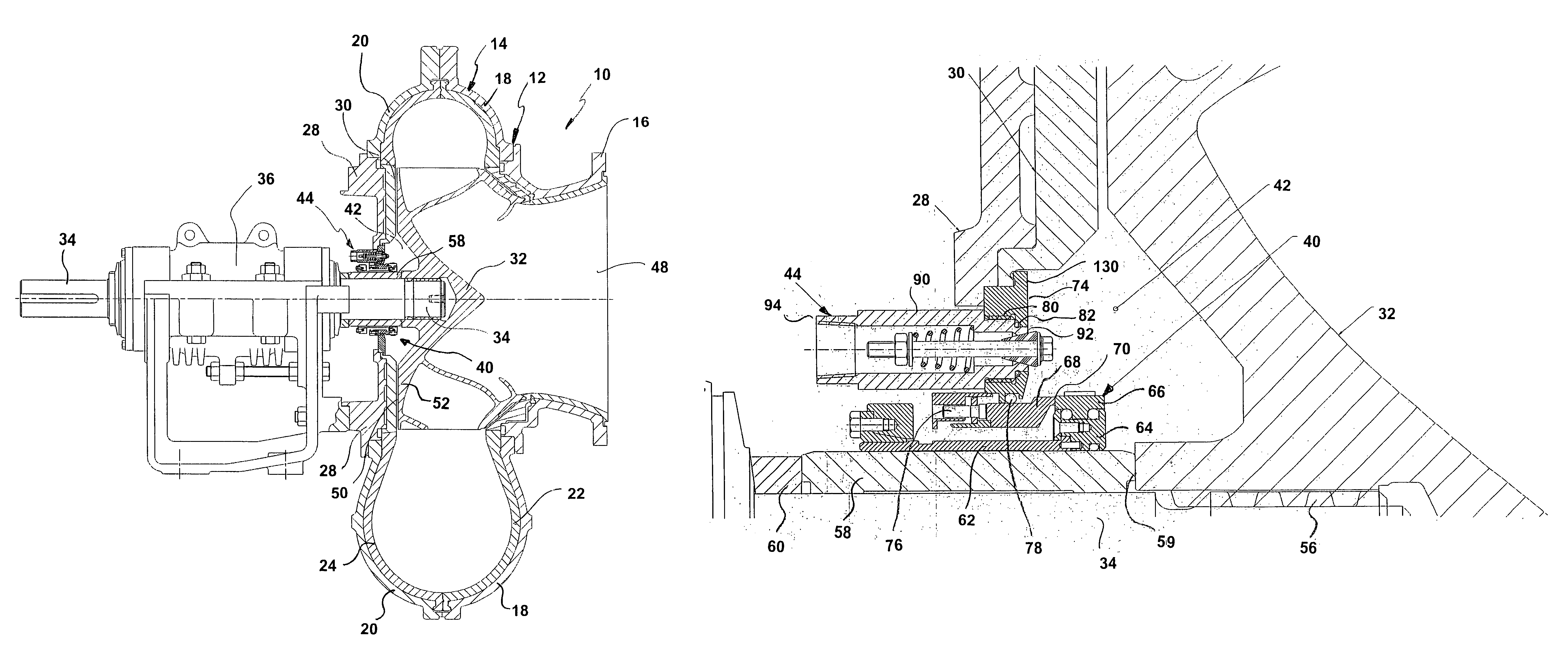
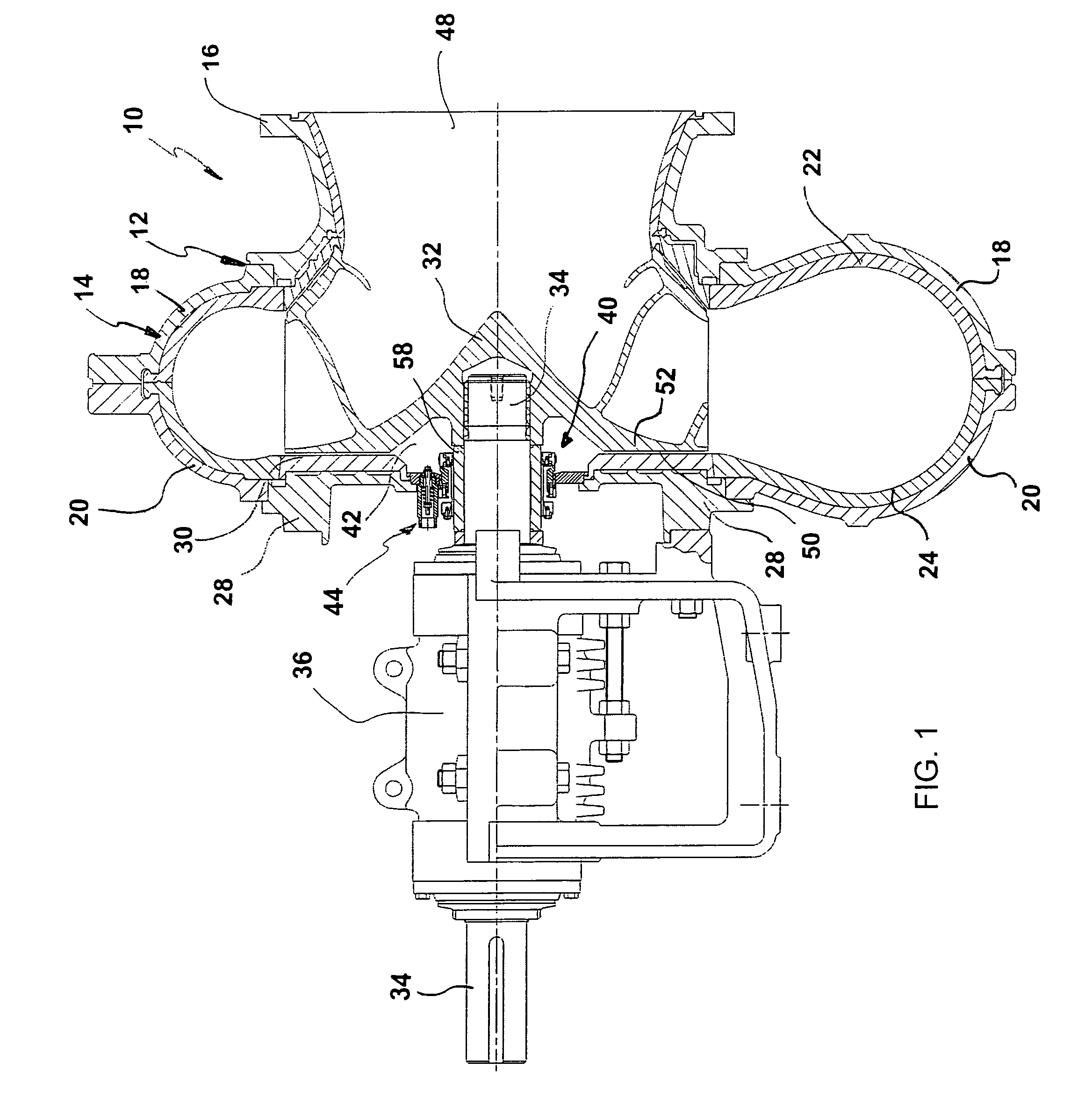
[0026]FIG. 1 illustrates, in partial cross section, a centrifugal pump 10 of the type used to process slurries. The pump 10 generally comprises a pump casing 12 which, in turn, comprises a volute casing 14 to which is attached to a suction inlet casing 16. As shown, the volute casing 14 may preferably comprise a front casing 18 and a back casing 20. In the particular embodiment of the pump 10 shown, casing liners 22, 24 are installed on the inner surface of the front casing 18 and back casing 20. The pump 10 further comprises a frame plate adaptor 28 that attaches to the back casing 20. A frame plate liner insert 30 is positioned adjacent the frame plate adaptor 28.

[0027]An impeller 32 is positioned in the pump casing 12 and is secured to a pump shaft 34 that extends through the frame plate adaptor 28. The pump shaft 34 also extends through a bearing housing 36 in which is located a set of bearings (not shown) which support the pump shaft 34. The pump shaft 34 is also keyed for atta...


PUM


Abstract

In a rotodynamic pump, a seal chamber conditioning valve mechanism is positioned at least partially within the seal chamber of the pump to selectively and intermittently deliver fluid to or discharge contents from the seal chamber to modify the condition or content of the seal chamber and effectively protect the mechanical seal from failure due to, for example, built up solids or the presence of air. The conditioning valve mechanism may be actuated by a control device in communication with monitoring apparatus that determines the condition of the seal chamber, and particularly the mechanical seal face.

Description

BACKGROUND OF THE INVENTION[0001]1. Field of the Invention[0002]This invention relates to rotodynamic pumps of the type typically used for processing or handling slurries. Specifically, this invention relates to structures and methods for controlling the conditions and content of a chamber surrounding the mechanical seal arrangement used with equipment such as rotodynamic pumps.[0003]2. Description of Related Art[0004]Rotodynamic pumps generally comprise an impeller which is connected to a drive shaft, and a pump casing in which the impeller rotates. Fluid processed by the pump can move to the area between the impeller and the drive side of the casing, around the drive shaft. Therefore, a mechanical seal arrangement is provided for sealing the drive shaft from leakage of fluid around the drive shaft. The mechanical seal of the drive shaft is often cooled and / or lubricated with a liquid flushed near the seal. Sometimes, the fluid used for flushing the system is that which is being pr...

Claims


Application Information

Patent Timeline
Patent Type & Authority Patents(United States)
IPC IPC(8): F01D11/00
CPCF04D29/128F04D29/126F04D7/02F04D15/00F04D29/00
Inventor BUSCHKOPF, KEVIN
Owner WEIR SLURRY GRP INC
Why Eureka
Try Eureka