Patterned thermal treatment using patterned cryogen spray and irradiation by light

a cryogen spray and thermal treatment technology, applied in the field of patterned thermal treatment using patterned cryogen spray and irradiation by light, can solve the problems of slow healing and other side effects, low risk of side effects, and difficulty in optimizing parameters, so as to avoid freezing or burning the tissue. , the effect of avoiding the effect of burning

Inactive Publication Date: 2010-08-24
RELIANT TECH INC
View PDF35 Cites 73 Cited by
  • Summary
  • Abstract
  • Description
  • Claims
  • Application Information

AI Technical Summary

Benefits of technology

[0015]Some designs are based on a handpiece. The patterned cryogen and the irradiating light are both delivered through the handpiece. The handpiece may include a velocity- or position-sensing element that triggers delivery of the cryogen and / or the light. Rapid cycling of heating and cooling cycles over a single area before the tissue temperature equilibrates can be implemented to advantageously avoid freezing or burning the tissue.

Problems solved by technology

If photothermal treatment uses a wide beam of light, particularly with a wavelength that is non-selective, such as a wavelength primarily absorbed within the tissue by water, it can be difficult to optimize the parameters to achieve treatment that is both effective and has a low risk of side effects.
If the delivered optical fluence is too high, the region can be overtreated, resulting in slow healing and other side effects.
If the delivered optical fluence is too low, the stimulation may be too weak to cause the desired treatment.
Thus, broad area photothermal treatment is limited in the levels of treatment that are simultaneously effective and safe.
Both of these systems are expensive and can be subject to precise alignment tolerances.
In addition, these systems can be painful.
In addition, moving parts in the scanning system can wear out, thus reducing reliability.
One limitation of fractional resurfacing technology is that the dermal-epidermal junction (DE junction) is the weakest portion of the skin.
High density fractional treatments can lead to separation of the DE junction, which can slow the healing process.
Very high density fractional treatments can approach broad area treatment and can suffer from similar side effects.

Method used


Image

  • Patterned thermal treatment using patterned cryogen spray and irradiation by light
  • Patterned thermal treatment using patterned cryogen spray and irradiation by light
  • Patterned thermal treatment using patterned cryogen spray and irradiation by light

Examples


Embodiment Construction

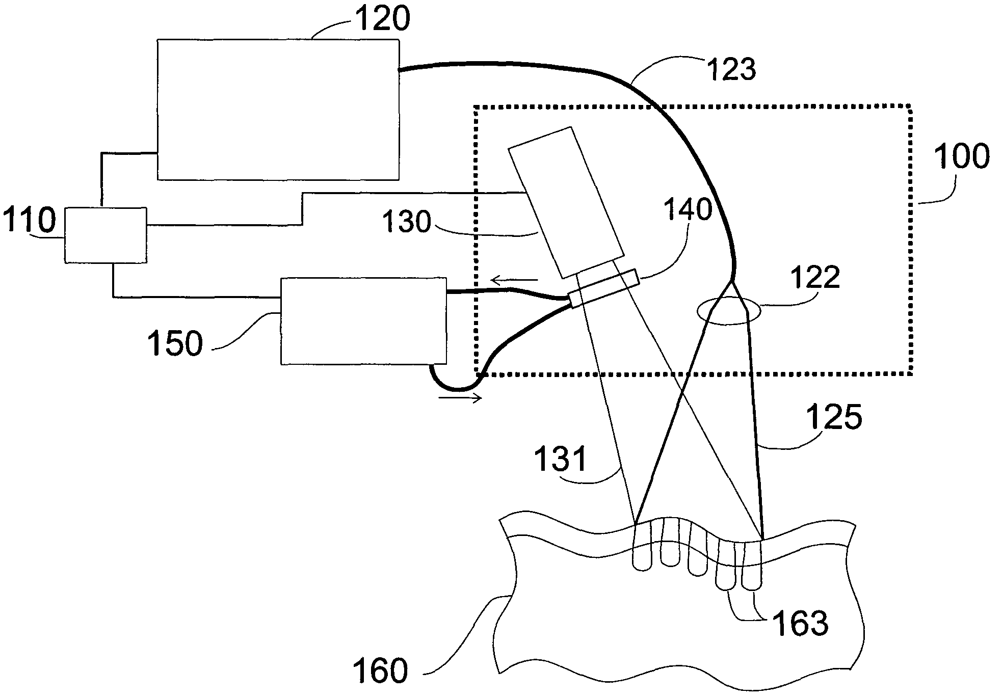
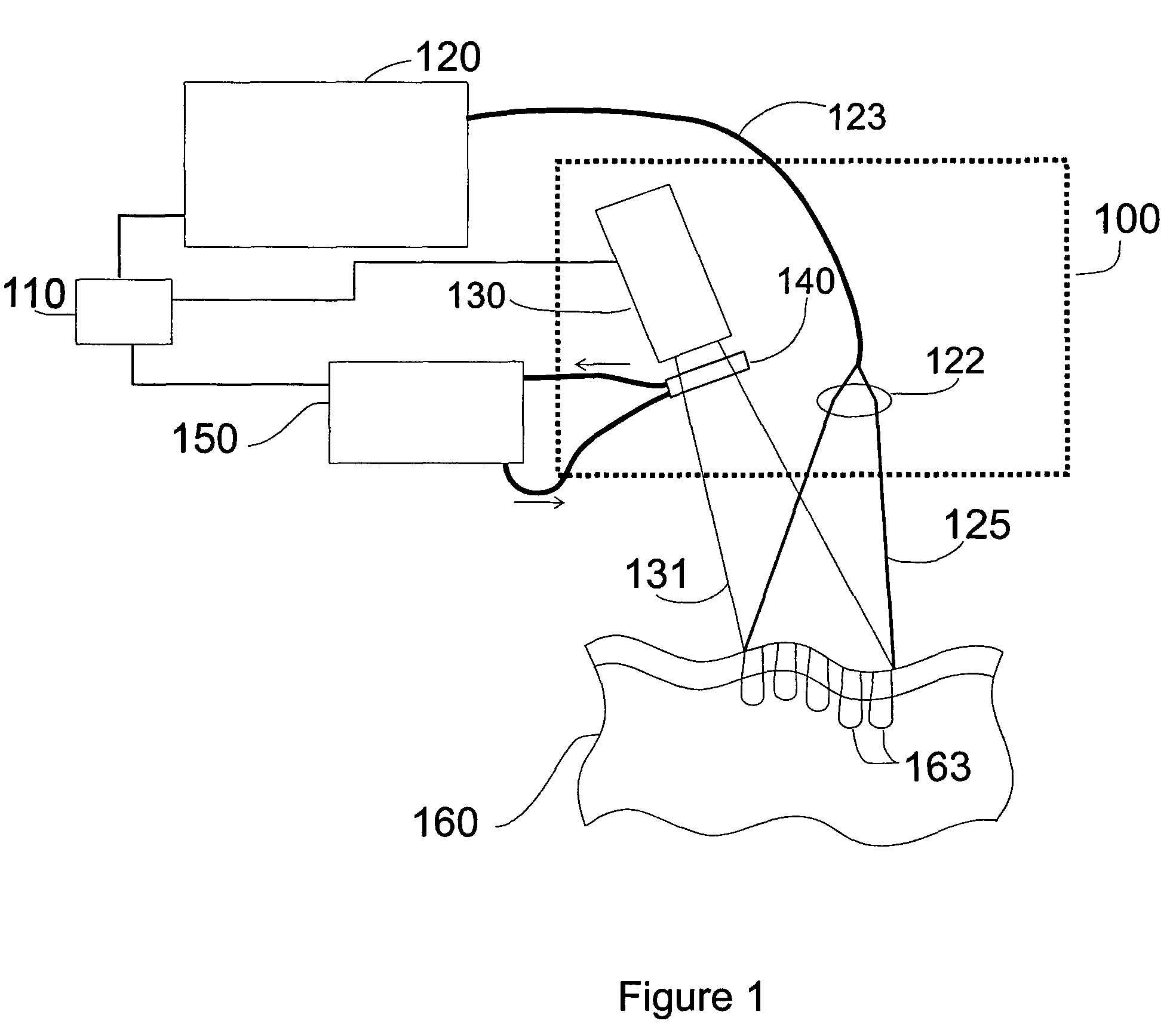
[0026]FIG. 1 illustrates an embodiment of the invention. This embodiment includes an optical delivery system and a cryogen delivery system. In the example of FIG. 1, the optical delivery system includes optical source 120. The optical delivery system of FIG. 1 also includes light guide 123 and lens 122. Light guide 123 delivers light 125 from the optical source 120 to the delivery lens 122. The delivery lens 122 delivers light 125 to a target tissue 160.

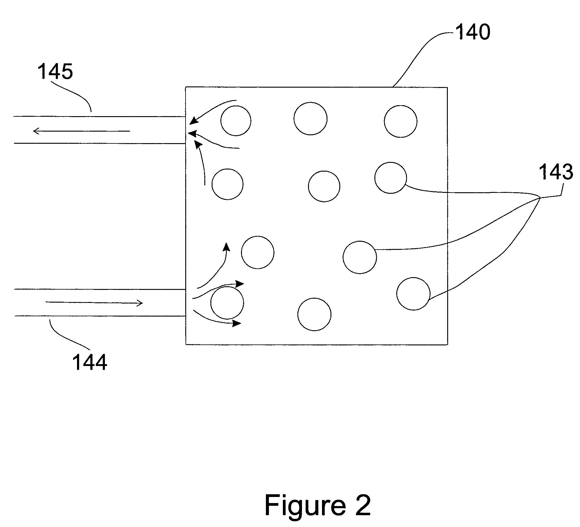
[0027]In the example of FIG. 1, the cryogen delivery system includes a cryogen container 130 and a patterning element. The cryogen delivery system of FIG. 1 includes a mask 140 as the patterning element. The cryogen delivery system of FIG. 1 also includes a temperature control system 150 for heating the mask 140. The cryogen container 130 is controlled by the control unit 110 and sprays a cryogen 131 towards a mask 140 and towards the target tissue 160. The mask 140 patterns the cryogen 131 by allowing part of the cryogen 131 to pass...


PUM


Abstract

A spray of cryogen is patterned to create a pattern of cooled regions on a target tissue for cosmetic dermatological treatment. In one embodiment, the cryogen is patterned using a heated mask. An optical source is configured to irradiate the target tissue in a region at least partially overlapping the cooled regions to create a pattern of treatment zones. A control unit adjusts the timing of between the cryogen and optical pulses.

Description

CROSS-REFERENCE TO RELATED APPLICATION[0001]This application claims priority under 35 U.S.C. §119(e) to U.S. Provisional Patent Application Ser. No. 60 / 635,143, “Spray Fractals Device and Method,” by Nikolai I. Tankovich, filed Dec. 10, 2004. The subject matter of the foregoing is incorporated herein by reference in its entirety.BACKGROUND OF THE INVENTION[0002]1. Field of the Invention[0003]This invention relates generally to creating fractional treatment using a patterned cooling spray and an optical source, for example by using a patterned cryogen spray with a laser source to create a pattern of microscopic treatment zones for cosmetic dermatological treatment.[0004]2. Description of the Related Art[0005]Light sources (e.g., lasers, LEDs, flashlamps, etc., including in the non-visible wavelengths such as infrared) are frequently used to treat biological tissues inside and outside the human body through a photothermal process that comprises heating the tissue using light absorbed ...

Claims


Application Information

Patent Timeline
Patent Type & Authority Patents(United States)
IPC IPC(8): A61B18/02A61B18/20
CPCA61B18/02A61B18/203A61B2018/00452A61B18/0218
Inventor TANKOVICH, NIKOLAI I
Owner RELIANT TECH INC
Why Eureka
Try Eureka