Regulator circuit and corresponding uses

a voltage or current regulator and circuit technology, applied in the direction of electric variable regulation, instruments, apparatus without intermediate ac conversion, etc., can solve the problems of limiting the application of the circuit, reducing amplification capacity, reducing efficiency, etc., to reduce the amount of necessary coils, reduce switching time requirements, and increase the effect of efficiency

Inactive Publication Date: 2010-08-24
BAOLAB MICROSYST
View PDF36 Cites 5 Cited by
  • Summary
  • Abstract
  • Description
  • Claims
  • Application Information

AI Technical Summary

Benefits of technology

[0013]they have a very low strength when they are closed and a very high strength when they are opened. That allows to highly improve the efficacy of the circuit as they minimize the losses due to the Joule effect both in the case of closed circuit and in the case of opened circuit.
[0014]they can work with voltages much higher than the voltages necessary for their activation. This allows generating voltages much higher than the circuit control voltages. Moreover, it is possible to connect a high amount of condensers in parallel (three or more condensers) and then to connect them simultaneously in series, whereby with only two switching steps one can obtain voltage increases as high as wished.
[0015]they allow a very high switching speed. Likewise that is a very important advantage, because the capacity of “pumping” more or less power (i.e., the intensity in case that the voltage is imposed) basically depends on two parameters: the condensers capacity and the “pumping” speed (of switching). The miniaturized relays have a very high switching speed, and that allows reducing the size of the condensers for a certain output power. Thus, the use of miniaturized relays allows a double size reduction: due to the miniaturized relays by themselves, and due to the use of smaller condensers.
[0017]the use of miniaturized relays requiring very little energy in order to be activated, such as for example those that will be described below, also allows to improve in an important extent the efficacy of the assembly, as in the praxis a regulator circuit will have a high amount of miniaturized relays that will be connecting and disconnecting at a high speed, whereby their electric consumption is a factor that can be significant if the selected relay is not of low consumption.
[0018]the use of miniaturized relays allows to clearly reduce the acoustic problem, and thus it is not necessary, in general, to include acoustic protections of shield type or the like in spite of having a high amount of relays connecting and disconnecting at a high speed.
[0022]Although in general reference has been made to the specific use of condensers, it must be taken into account that the use of condensers is only a preferred solution. In general, the circuit can have any type of reactances: condensers, coils or even combinations of both. In case of using coils, these can be connected in series and can be charged with current in order to be subsequently connected in parallel and to obtain a final current that would be the initial current (that passes through the series coils) multiplied by the number of coils connected in parallel. That would allow obtaining a current source, that could be of interest as such, or it could be subsequently adapted in order to be able to operate as voltage source. Preferably coils made with superconductive material would be used, and that would allow to reduce the amount of necessary coils, to reduce the switching time requirements of the miniaturised relays, to increase the efficacy as there are not any energetic losses in the coils, and to make possible that all the regulator circuit would be integrated.

Problems solved by technology

However, the known circuits in the state of the art have several drawbacks that limit their possible applications:they have reduced efficienciesthey have a reduced amplification capacitythey have a very reduced power,they are very bigthey are noisy

Method used


Image

  • Regulator circuit and corresponding uses
  • Regulator circuit and corresponding uses
  • Regulator circuit and corresponding uses

Examples


Embodiment Construction

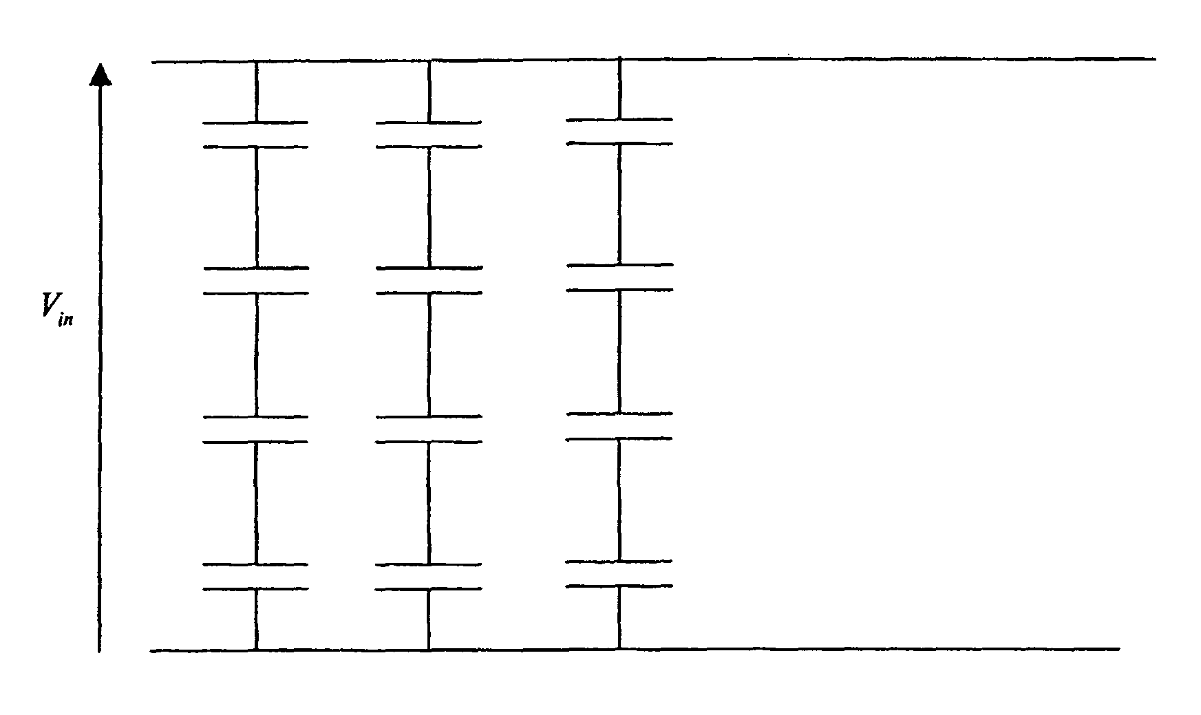
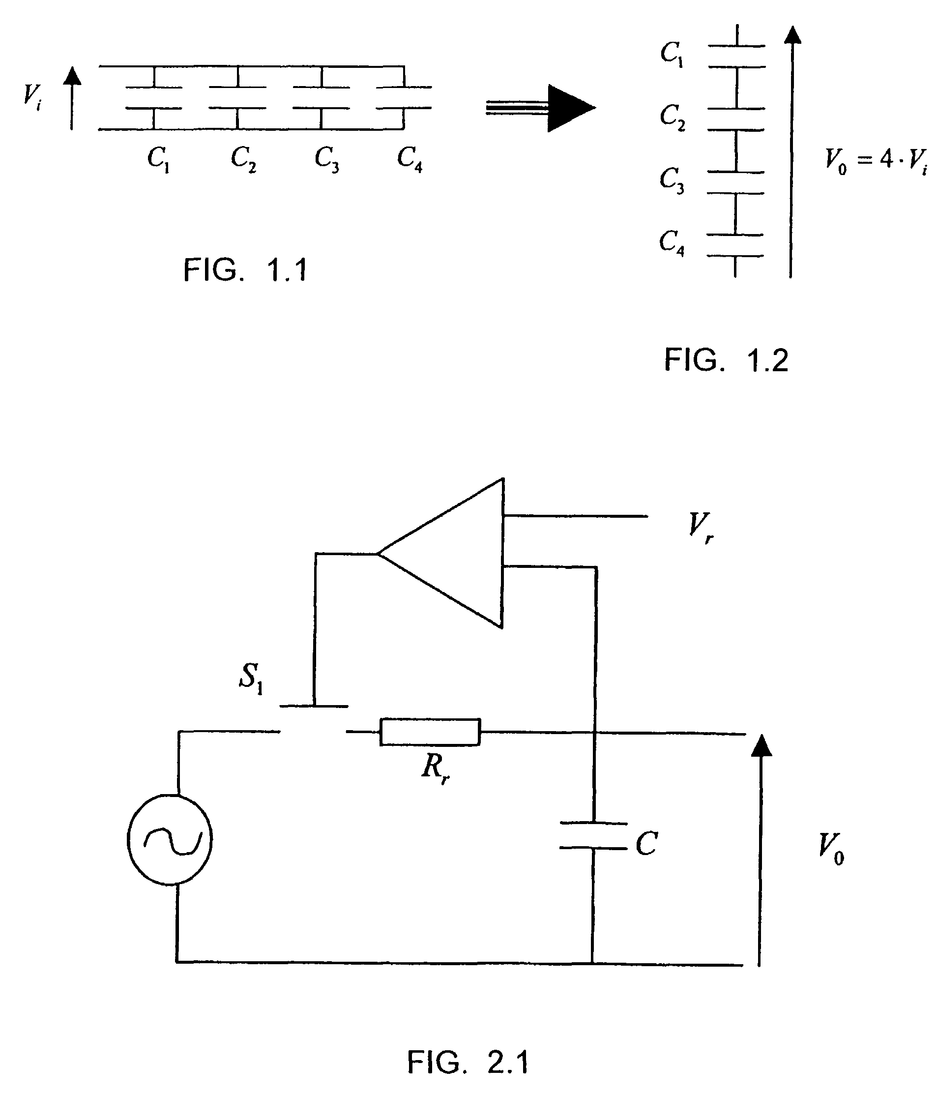
[0056]FIGS. 1.1 and 1.2 show the basic concept of charge pumps: a circuit comprising two input terminals and a plurality of condensers C1, C2, C3, C4 series connected with the input terminals. All the condensers are charged at a voltage Vi and subsequently the circuit is connected again so that the condensers are in parallel. The voltage in output terminals Vo is four times the voltage Vi. Furthermore, doing the sequence in a reverse way, it is possible to divide the voltage by four. In these schemes neither all the interconnection or the corresponding relays have been shown because a plurality of them must exist in order to allow all the required connections.

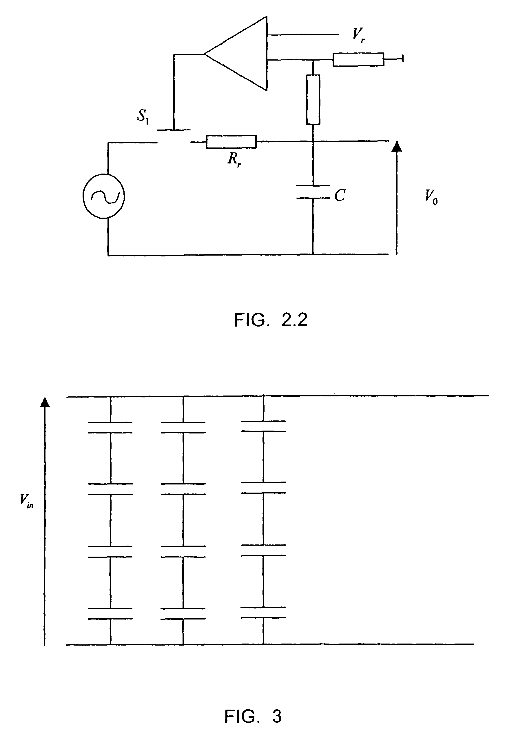
[0057]With this type of circuit it is possible to increase or reduce the output voltage in a discrete manner: as multiples of the input voltage or as divisions of the input voltage by an integer. Thus, a preferred solution of a regulator circuit according to the invention comprises voltage monitoring means of at least one of th...


PUM


Abstract

Regulator circuit and corresponding uses. The regulator circuit includes at least two input terminals, at least two reactances, at least two output terminals, a plurality of interconnections for connecting said reactances with respect to one another and for connecting at least one of the reactances with the input and output terminals. The interconnections include miniaturized relays that allow exchanging a series connection of the reactances for a parallel connection and vice versa. The circuit can include a voltage monitor, power supply modules, input and output protectors, reference signal modules, and control modules. The regulator circuit has multiple applications including charge pump, power supply, DC / DC converter, DC / AC converter, AC / DC converter, D / A converter, A / D converter, and power amplifier.

Description

FIELD OF THE INVENTION[0001]The invention relates to a voltage or current regulator circuit, comprising at least two input terminals, at least a first group of reactances with at least two reactances, at least two output terminals, a plurality of interconnections suitable for connecting said reactances with respect to one another and suitable for connecting at least one of said reactances with said input and output terminals. The invention also refers to preferred uses of a regulator circuit according to the invention.STATE OF THE ART[0002]Circuits, usually called charge pumps or voltage pumps, wherein there are provided several condensers that can be charged at a certain voltage by an external source and that, once charged, they are connected to a certain charge that must be supplied are known. Suitable interconnections allow supplying to the charge a voltage different from the voltage of the external source. Indeed: if the condensers are parallel connected and are connected to the...

Claims


Application Information

Patent Timeline
Patent Type & Authority Patents(United States)
IPC IPC(8): G05F3/00H02M3/06
CPCH02M3/06
Inventor MONTANYA SILVESTRE, JOSEP
Owner BAOLAB MICROSYST
Why Eureka
Try Eureka