Double-wall protection levee system

a technology of double-wall protection and levees, applied in excavations, artificial islands, foundation engineering, etc., can solve the problems of altering the amount of ground penetration needed, and achieve the effects of reducing transverse movement, increasing the resistance of the connected pair of piles, and protecting against scour

a technology of double-wall protection and levees, applied in excavations, artificial islands, foundation engineering, etc., can solve the problems of altering the amount of ground penetration needed, and achieve the effects of reducing transverse movement, increasing the resistance of the connected pair of piles, and protecting against scour

US7785042B2Active Publication Date: 2010-08-31SCANDALIATO SAMUEL ZENGEL

Image

  • Double-wall protection levee system
  • Double-wall protection levee system
  • Double-wall protection levee system

Examples


Embodiment Construction

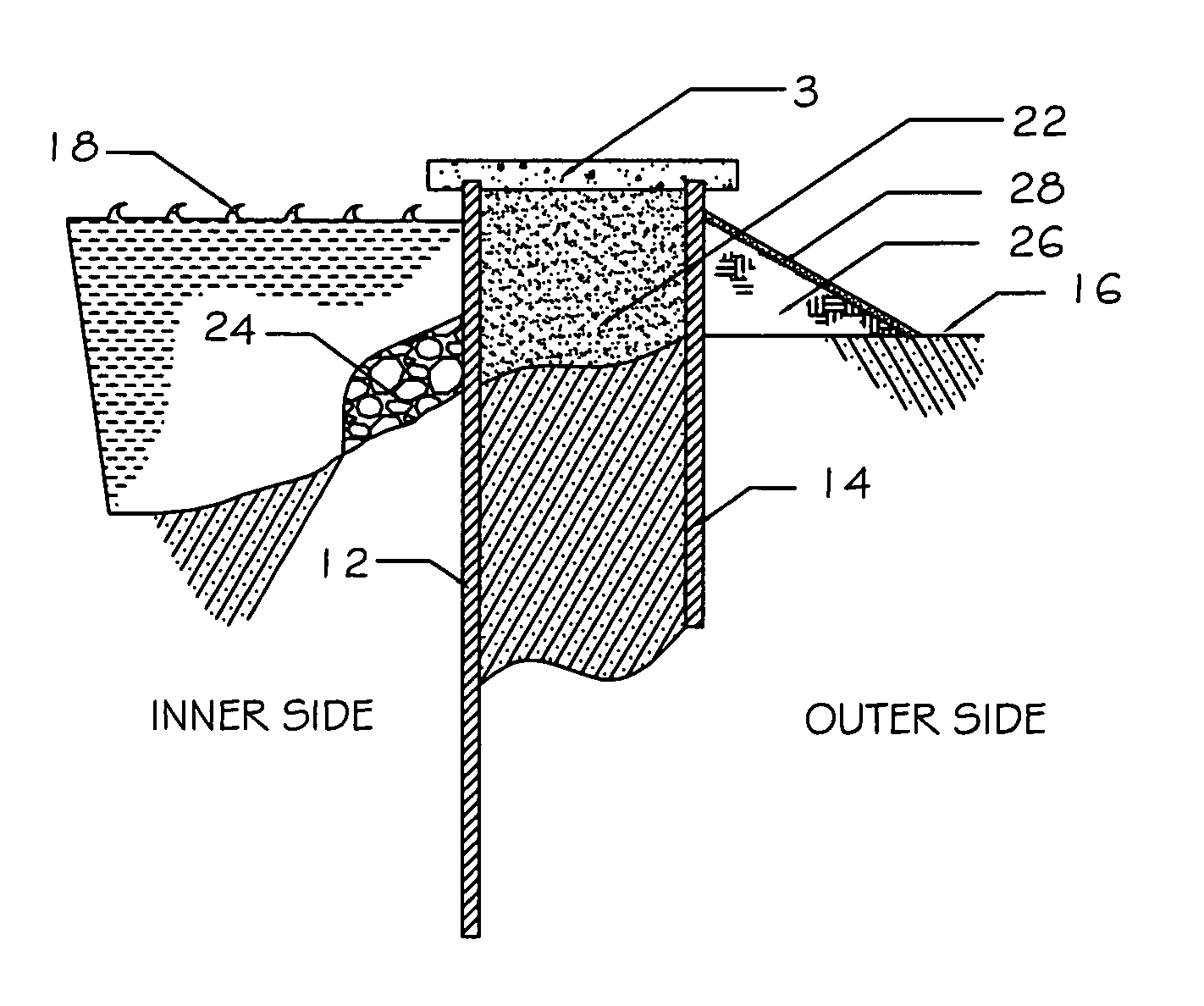
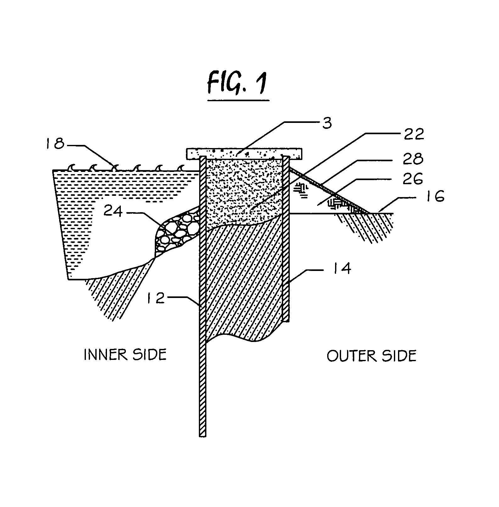
[0023]A pair of piles, inner pile 12, also referred to as tension pile 12, and outer pile 14, also referred to as compression pile 14, are substantially flat, sheet-type piles. Piles 12 and 14 are placed, preferably by driving, into natural ground 16 at the bank of water body 18 (shown as a canal) or, alternatively, into a levee at the bank of a water body. Piles 12 and 14 are preferably made of sheet steel, but they can also be made of wood, plastic, concrete, or a polymer. Pairs of piles 12 and 14 are oriented with broad, sheet faces parallel to each other and are positioned transversely, that is they are separated by approximately three feet to approximately twenty feet.

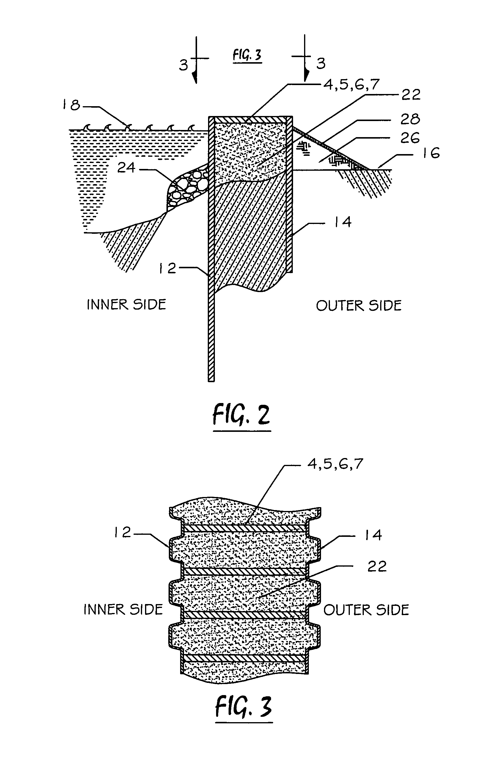
[0024]As shown in FIG. 1, piles 12 and 14 are rigidly connected together by a connector, preferably reinforced concrete cap 3. In the alternative embodiment depicted in FIGS. 2 and 3, strut 4, either steel beam 5 or steel pipe 6 or tube 7 can be used to connect piles 12 and 14 together. The connector preferably ha...


PUM


Abstract

A double-wall protection levee floodwall has a pair of piles placed into soil at the bank at the edge of a water body or formed by a levee. The piles of the pair are oriented parallel to each other, are spaced apart transversely, and are rigidly connected together by a connector so that when the force of rising water or a water-borne object is applied to a face of one of the piles, a force couple develops that places one of the piles in tension and the other pile of the pair in compression. The distance between the force-coupled piles and the depth of the piles in the soil provide the ability to withstand predetermined transverse forces while conserving materials and space. Fill material, riprap, earthen support, and erosion control matting can improve the function of the double-wall floodwall. Multiple pairs of piles can be longitudinally placed to form a continuous floodwall.

Description

CROSS-REFERENCE TO RELATED APPLICATIONS[0001]NoneSTATEMENT REGARDING FEDERALLY SPONSORED RESEARCH[0002]NoneNAMES OF PARTIES TO A JOINT RESEARCH AGREEMENT[0003]NoneREFERENCE TO A “SEQUENCE LISTING”[0004]NoneBACKGROUND OF THE INVENTION[0005]1. Field of the Invention[0006]The invention relates to flood control systems and apparatus and, more particularly, to a method of using coupled piles to form a flood barrier, a system embodying the method, and apparatus for use in the method and system.[0007]2. Description of Related Art, Including Information Disclosed Under 37 CFR 1.97 and 37 CFR 1.98[0008]The effect of normal compaction of alluvial soil over time is exacerbated by river levees that prevent the seasonal deposit of new sediment and by extraction of subsurface minerals, particularly oil. Coastal wetland erosion, whether due to salt-water intrusion resulting from man-made canals and waterways or to a failure to replenish wetland soils after subsidence, provides a channel or at leas...

Claims


Application Information

Patent Timeline
31 Aug 2010
Publication
US7785042B2
IPC
E02D5/02
CPC
E02B3/102; E02B3/10; Y02A10/11
Inventors
SCANDALIATO, SAMUEL ZENGEL