Gas injection system for plasma processing

a plasma processing and gas injection technology, applied in dental surgery, lighting and heating apparatus, combustion types, etc., can solve the problems of process drift, unfavorable uniform etching and deposition, and the orifice located at the distal end of the injector tub

Inactive Publication Date: 2010-08-31
LAM RES CORP
View PDF40 Cites 36 Cited by
  • Summary
  • Abstract
  • Description
  • Claims
  • Application Information

AI Technical Summary

Benefits of technology

[0015]The invention provides a plasma processing system which includes a plasma processing chamber, a vacuum pump connected to the processing chamber, a substrate support supporting a substrate within the processing chamber, a dielectric member having an interior surface facing the substrate support, wherein the dielectric member forms a wall of the processing chamber, a gas injector extending through the dielectric member such that a distal end of the g...

Problems solved by technology

This can lead to an undesirable loss in etch and deposition uniformity.
These conduit arrangements can cause process drift problems as a result of heating of the ends of the conduits.
Injectors with the orifices located at the distal ends of the injector tubes may be prone to clogging after processing a relatively small batch of substrates, e.g., less than 100.
This injector orifice clogging is detrimental as it can lead to nonuniform distribution of reactants, nonuniform film deposition or etching of the substrate, and shifts in the overall deposition or etch rate.
While these systems are intended to improve process uniformity, they suffer from the drawbacks noted above, namely clogging of the orifices at the distal ends of the injectors, which can adversely affect film uniformity on the substrat...

Method used


Image

  • Gas injection system for plasma processing
  • Gas injection system for plasma processing
  • Gas injection system for plasma processing

Examples


Embodiment Construction

[0026]The present invention provides an improved gas injection system for plasma processing of substrates such as by etching or CVD. The injection system can be used to inject gases such as gases containing silicon, halogen (e.g., F, Cl, Br, etc.), oxygen, hydrogen, nitrogen, etc. The injection system can be used alone or in addition to other reactant / inert gas supply arrangements.

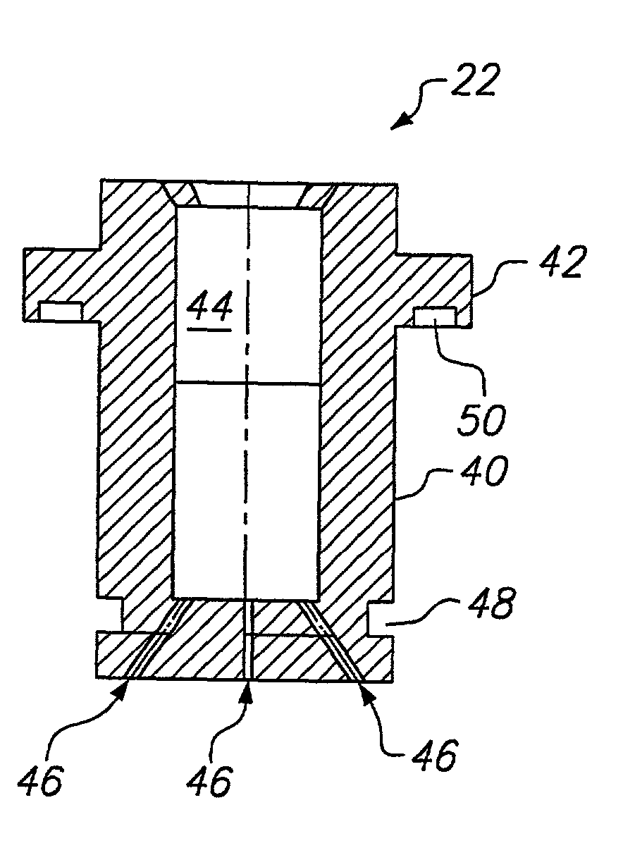
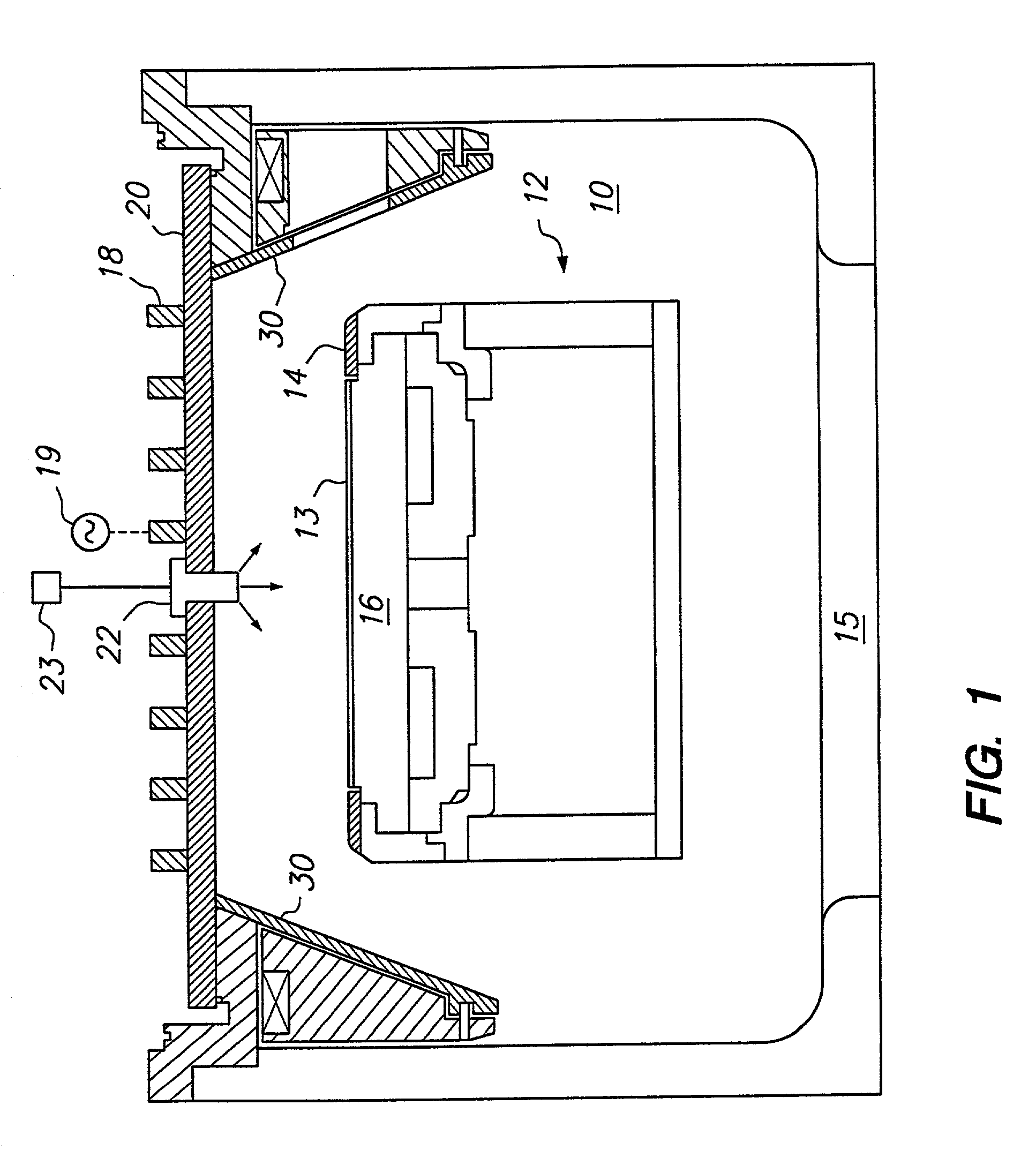
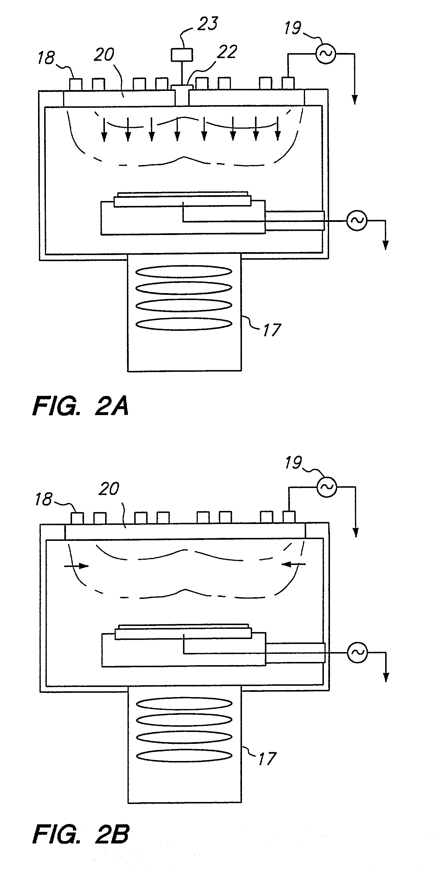
[0027]According to a preferred embodiment of the invention, a gas injection arrangement is provided for an inductively coupled plasma chamber. In the preferred arrangement, a gas injector is centrally located in an upper wall of the chamber and one or more gas outlets direct process gas into the chamber above a semiconductor substrate to be processed. The gas injector in accordance with the invention can improve etch uniformity, center-to-edge profile uniformity, critical dimension (CD) bias and / or profile microloading.

[0028]The gas outlets can be provided in a surface of the gas injector which is below, f...


PUM

PropertyMeasurementUnit
Angleaaaaaaaaaa
Angleaaaaaaaaaa
Areaaaaaaaaaaa

Abstract

A plasma processing system for plasma processing of substrates such as semiconductor wafers. The system includes a plasma processing chamber, a substrate support for supporting a substrate within the processing chamber, a dielectric member having an interior surface facing the substrate support, the dielectric member forming a wall of the processing chamber, a gas injector fixed to, part of or removably mounted in an opening in the dielectric window, the gas injector including a plurality of gas outlets supplying process gas into the chamber, and an RF energy source such as a planar or non-planar spiral coil which inductively couples RF energy through the dielectric member and into the chamber to energize the process gas into a plasma state. The arrangement permits modification of gas delivery arrangements to meet the needs of a particular processing regime. In addition, compared to consumable showerhead arrangements, the use of a removably mounted gas injector can be replaced more easily and economically.

Description

[0001]This application is a continuation, of application Ser. No. 09 / 223,273, filed Dec. 30, 1998 now U.S. Pat. No. 6,230,651.FIELD OF THE INVENTION[0002]The present invention relates to a system and a method for delivering reactants to a substrate in a plasma processing system for semiconductor substrates such as semiconductor wafers. More particularly, the present invention relates to a system and a method for delivering reactants via a gas injection system to maximize processing uniformity and efficiency.BACKGROUND OF THE INVENTION[0003]Vacuum processing chambers are generally used for etching or chemical vapor depositing (CVD) of materials on substrates by supplying process gas to the vacuum chamber and applying a radio frequency (RF) field to the gas. Showerhead gas injection and diffusive transport systems are commonly used to ensure even distribution over the substrate.[0004]U.S. Pat. No. 4,691,662 to Roppel et al. discloses a dual plasma microwave apparatus for etching and d...

Claims


Application Information

Patent Timeline
IPC IPC(8): C23C16/455C23C16/44C23C16/06C23C16/22B01J19/08H05H1/46C23C16/507H01J37/32H01L21/205H01L21/302H01L21/3065
CPCH01J37/3244H01L21/205
Inventor NI, TUQIANGDEMOS, ALEX
Owner LAM RES CORP
Why Eureka
Try Eureka