Systems and methods for utilizing activity detection information in relation to image processing

a technology of activity detection and image processing, applied in the field of image acquisition and processing, can solve the problem of reducing bandwidth for the sake of quality, and achieve the effects of reducing exposure time or integration time, reducing motion blur, and eliminating motion blur

Active Publication Date: 2010-09-07
TRANSCHIP ISRAEL
View PDF13 Cites 12 Cited by
  • Summary
  • Abstract
  • Description
  • Claims
  • Application Information

AI Technical Summary

Benefits of technology

[0005]The present invention provides systems and methods for receiving, processing, and / or transmitting video images using a central motion estimation and / or detection engine. The present invention provides a variety of functional advantages aided by a motion detection and / or estimation engine. For example, motion blur can be reduced or eliminated by using motion information provided from the motion estimation and / or detection engine. In one particular case, motion blur can be reduced by reducing exposure time or integration time, during which pixels in an imaging array are gathering light or other energy, and by increasing gains associated with the pixel processing. Reducing the integration time bounds the amount of motion that can occur in a detected scene.
[0006]As another example, information from the motion estimation and / or detection engine can be used in relation to video compression. Such motion estimation can include the most computationally significant part of a video compression encoder. In accordance with some embodiments of the present invention, the motion estimation and / or detection engine is implemented, either in whole or in part, outside of a corresponding video compression encoder. Thus, the complexity and physical size of the design can be reduced.
[0007]As yet another example, information from the motion estimation and / or detection engine can be used to perform compression mode adaptation. This can include, but is not limited to, adjusting a frame-rate to balance between transmission bandwidth and transmission quality. For example, when a scene contains moving objects, the quantization may be increased, which reduces bandwidth for sake of quality.
[0009]Yet further examples can include powering a camera device based on information provided by the motion estimation and / or detection engine. This can include, but is not limited to, adjusting the frame-rate and / or frame dimensions according to the scene content. In one particular example, such an approach is used in surveillance applications where video is transmitted only when scene change is detected. This approach reduces bandwidth requirements and power consumption. As another example, frame-rate can be adjusted to match the velocity of objects in a scene. Such an approach reduces bandwidth and power consumption, while retaining important details in a scene. In another particular example, only portions of a scene that include movement are transmitted. Power and bandwidth can be saved where only a portion of a frame is computed and / or transmitted.
[0010]Additional examples can include providing super resolution, or sub-pixel resolution using motion information provided from the motion estimation and / or detection engine. In this process, registration between two frames is provided, similar to that provided in the estimation of global motion in the previously discussed anti-shake process. By performing the motion estimation external to the super resolution processor, the complexity and size of such a processor can be reduced.
[0015]Other embodiments of the present invention provide imaging systems that include an image acquisition system that generates an image signal. The systems further include a motion estimation and / or detection system that is operable to estimate motion based on the image signal, and operable to generate a motion signal. In addition, the systems include a processing system that generates an output image. Such a processing system can include one or more of an anti-blur engine, an anti-shake engine, and / or a scene definition engine. Further, in some cases, the image acquisition system comprises an image detection array and a converter. Where an anti-blur engine is employed, a gain associated with the converter can be adjusted based on the motion signal. In some cases, the anti-blur engine may further modify the exposure duration in the image detection array.

Problems solved by technology

For example, when a scene contains moving objects, the quantization may be increased, which reduces bandwidth for sake of quality.

Method used


Image

  • Systems and methods for utilizing activity detection information in relation to image processing
  • Systems and methods for utilizing activity detection information in relation to image processing
  • Systems and methods for utilizing activity detection information in relation to image processing

Examples


Embodiment Construction

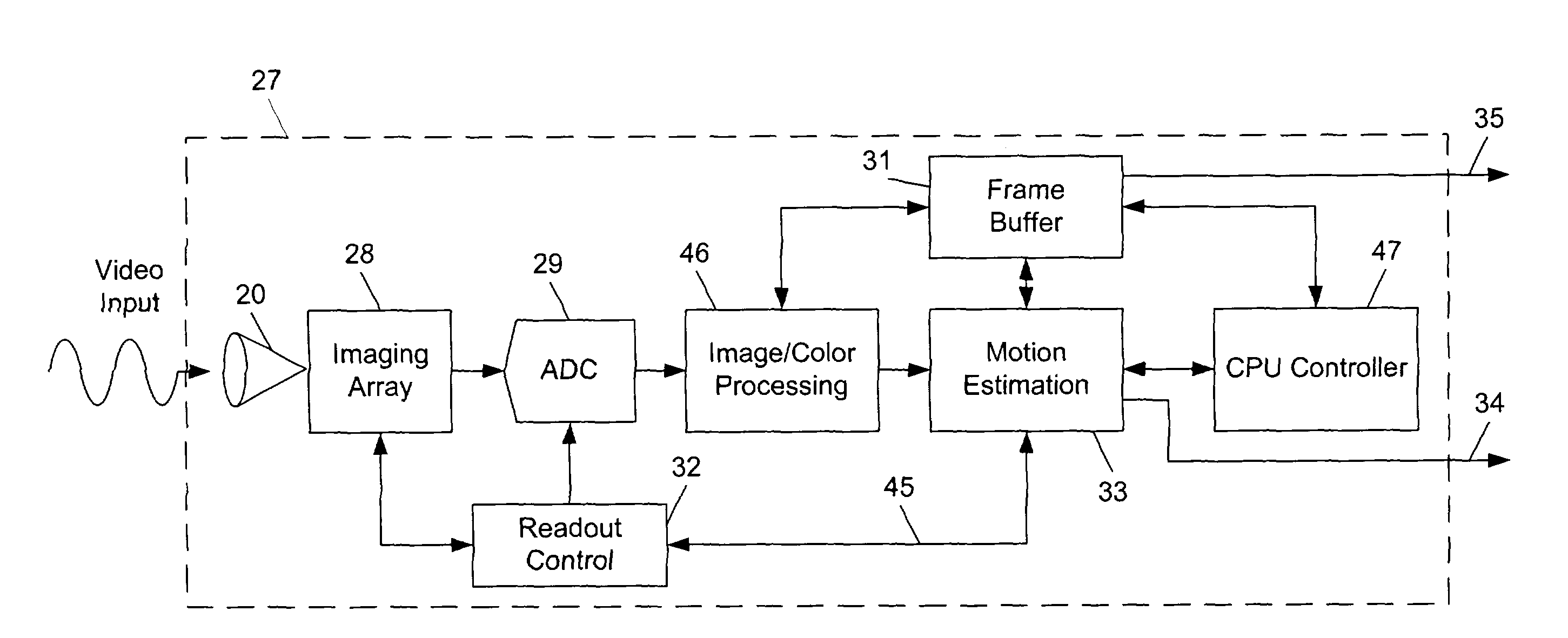
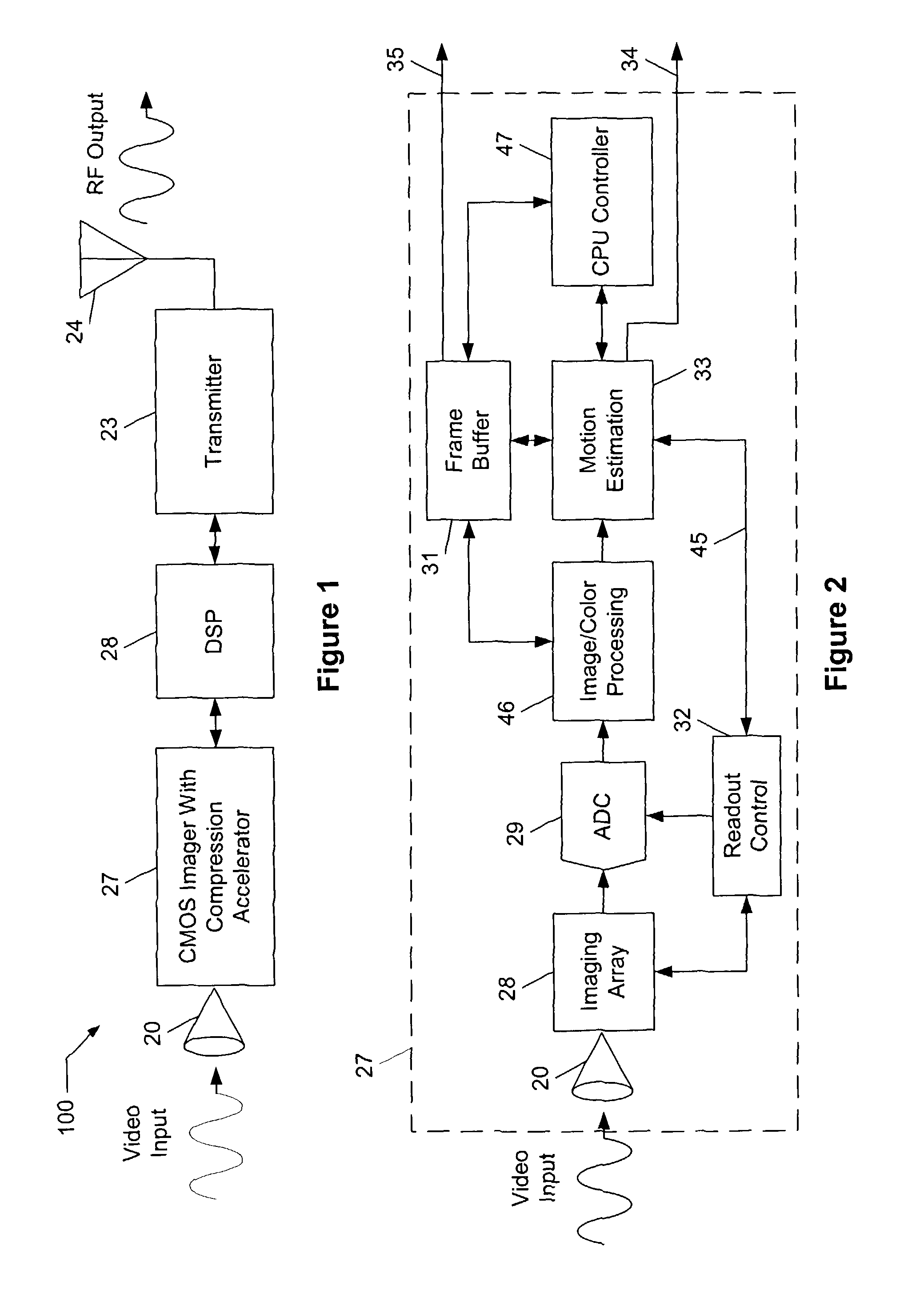
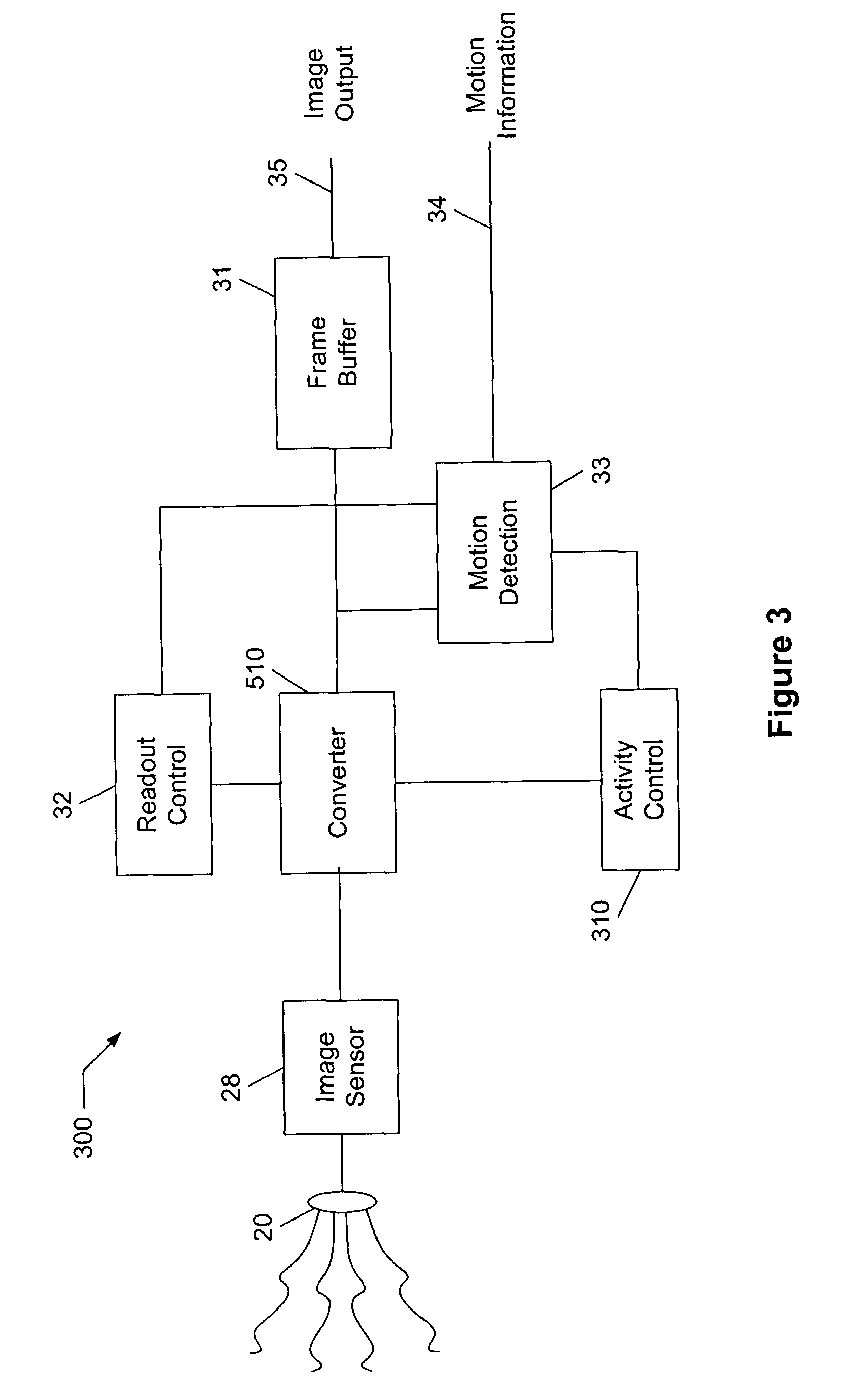
[0025]The present invention provides systems and methods for receiving, processing, and / or transmitting video images using a central motion detection and / or estimation engine. The present invention provides a variety of functional advantages aided by a motion estimation and / or detection engine. For example, motion blur can be reduced or eliminated by using motion information provided from the motion estimation and / or detection engine. In one particular case, motion blur can be reduced by reducing exposure time, or integration time, during which pixels in an imaging array are gathering light. Reducing the integration time bounds the amount of motion that can occur in a detected scene to a limited period.

[0026]As another example, information from the motion estimation and / or detection engine can be used in relation to video compression. Such motion estimation can include the most computationally significant part of a video compression encoder. In accordance with some embodiments of th...


PUM


Abstract

Imaging systems and methods for processing images. Various of the imaging systems include a motion detection and / or estimation engine. Information from such a motion engine can be used by one or more of a scene definition engine, a blur reduction engine, an anti-shake engine, and a video compression engine. Various of the methods include processes for accepting motion information from a motion detection and / or estimation engine and performing one or more of the following functions: anti-shake, blur reduction, scene definition, video compression, and power management. In some cases, the various systems and methods can be implemented on a single chip.

Description

CROSS-REFERENCES TO RELATED APPLICATIONS[0001]This application claims priority to U.S. Provisional Application No. 60 / 355,185, filed Feb. 8, 2002, and entitled “SYSTEMS AND METHODS FOR ACTIVITY DETECTION AND MOTION DRIVEN CONTROL”; and is a continuation-in-part of U.S. application Ser. No. 10 / 333 942, entitled “CMOS IMAGE SENSOR SYSTEM FOR VIDEO COMPRESSION”, filed on Jan. 23, 2003, which claims priority to PCT / US01 / 29170, filed Sep. 12, 2001, entitled “CMOS IMAGE SENSOR SYSTEM FOR VIDEO COMPRESSION”, which in turn claims priority from U.S. Provisional Application No. 60 / 231,778, filed Sep. 12, 2000, entitled “CMOS IMAGE SENSOR SYSTEM FOR VIDEO COMPRESSION”. Each of the aforementioned applications is assigned to an entity common hereto, and is incorporated herein by reference for all purposes.BACKGROUND OF THE INVENTION[0002]The present invention relates generally to the area of image acquisition and processing, and in particular to image acquisition and processing performed by semi...

Claims


Application Information

Patent Timeline
Patent Type & Authority Patents(United States)
IPC IPC(8): H04N5/228H04N7/12H04N5/14H04N5/21H04N5/232H04N5/235H04N5/353H04N5/359H04N7/26H04N7/36
CPCH04N5/144H04N5/21H04N5/23241H04N5/23248H04N5/23254H04N19/85H04N5/2353H04N5/335H04N19/503H04N19/137H04N19/537H04N5/2327H04N23/651H04N23/684H04N23/6811H04N23/68H04N23/73H04N25/42H04N25/00
Inventor VORONOV, GERMANARIEL, VIKTOR
Owner TRANSCHIP ISRAEL
Why Eureka
Try Eureka