Current limit protection apparatus and method for current limit protection

a current limit protection and current limit technology, applied in the field of current limit protection apparatus, can solve the problems of unusable peripheral devices of the computer system that cannot work normally computer system unable to recover to a normal mode from a sleeping mode, etc., to achieve smooth recovery to a normal mode, avoid overloading of the power supply under a sleeping mode

Active Publication Date: 2010-09-07
NUVOTON
View PDF5 Cites 9 Cited by
  • Summary
  • Abstract
  • Description
  • Claims
  • Application Information

AI Technical Summary

Benefits of technology

[0009]The present invention is directed to a current limit protection apparatus and a method thereof, by which overloading of a power supply under a sleeping mode can be avoided, and a computer system may smoothly recover to a normal mode from the sleeping mode.
[0014]In the present invention, a plurality of current threshold values is defined, and the supplied currents of different values can be selected according to the indicating signal. If the present invention is applied to the USB connection port, the current supplied to the USB peripheral device can be limited according to an operation mode of the computer system, and overloading of the power supply during the sleeping mode may be avoided, such that the computer system may smoothly recover to the normal mode from the sleeping mode.

Problems solved by technology

Accordingly, the necessary peripheral devices of the computer system cannot work normally due to lack of basic power, and the computer system then cannot recover to a normal mode from the sleeping mode.
However, some USB peripheral devices in the market still do not comply with an USB specification in which only 2.5 mA is allowed to be consumed during the sleeping mode, which causing the computer system unable to recover to the normal mode from the sleeping mode.

Method used


Image

  • Current limit protection apparatus and method for current limit protection
  • Current limit protection apparatus and method for current limit protection
  • Current limit protection apparatus and method for current limit protection

Examples


Embodiment Construction

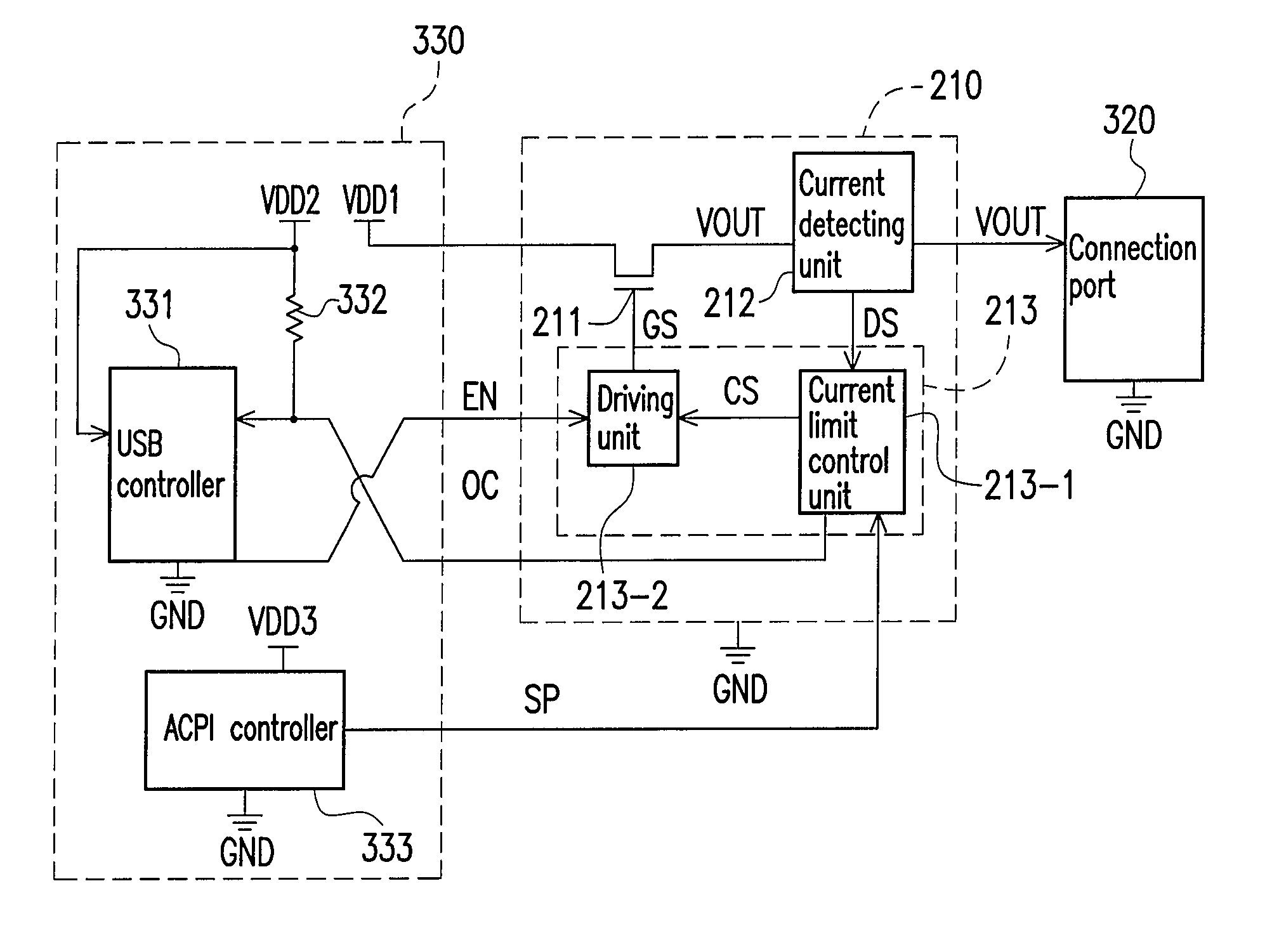
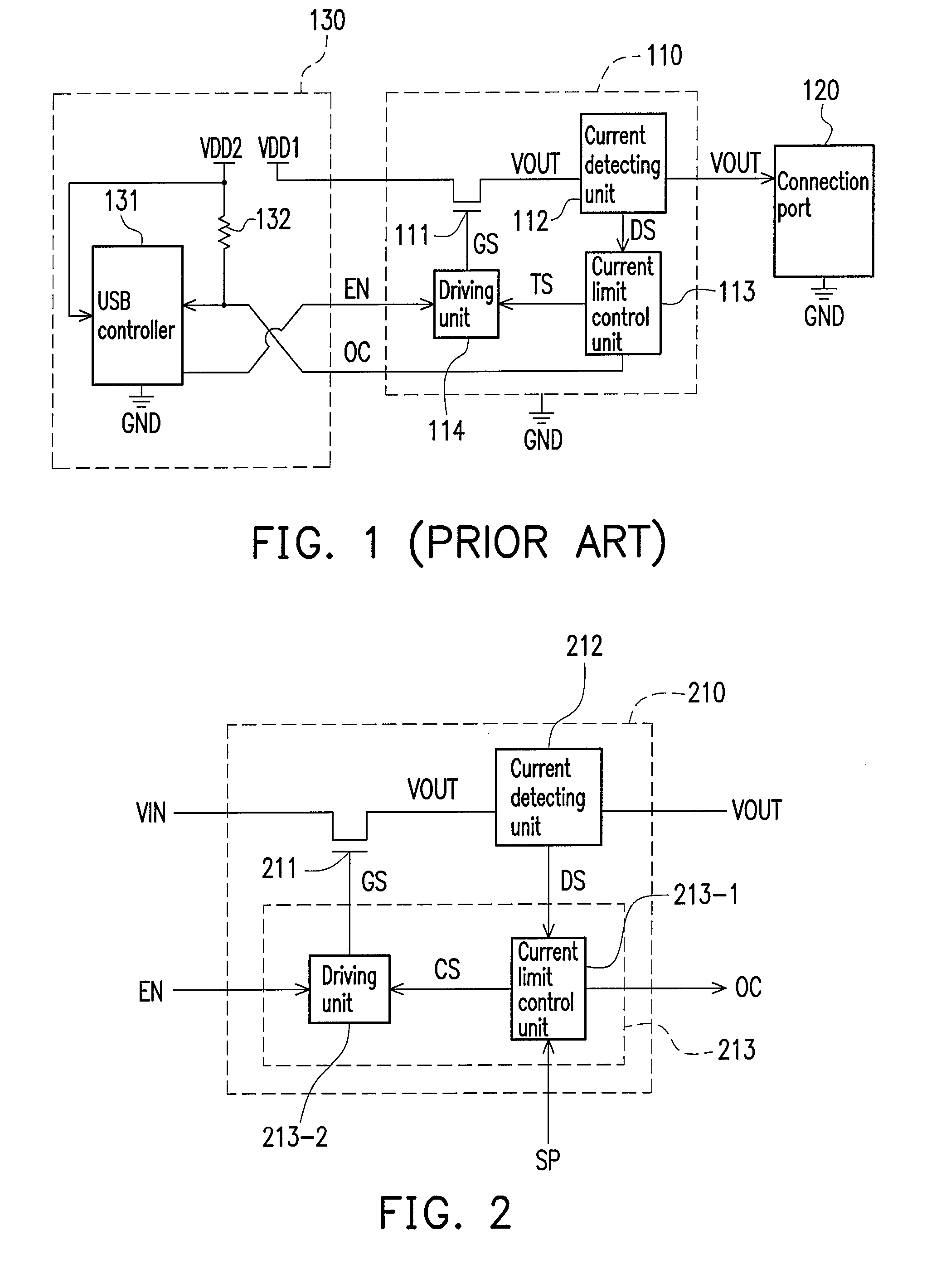
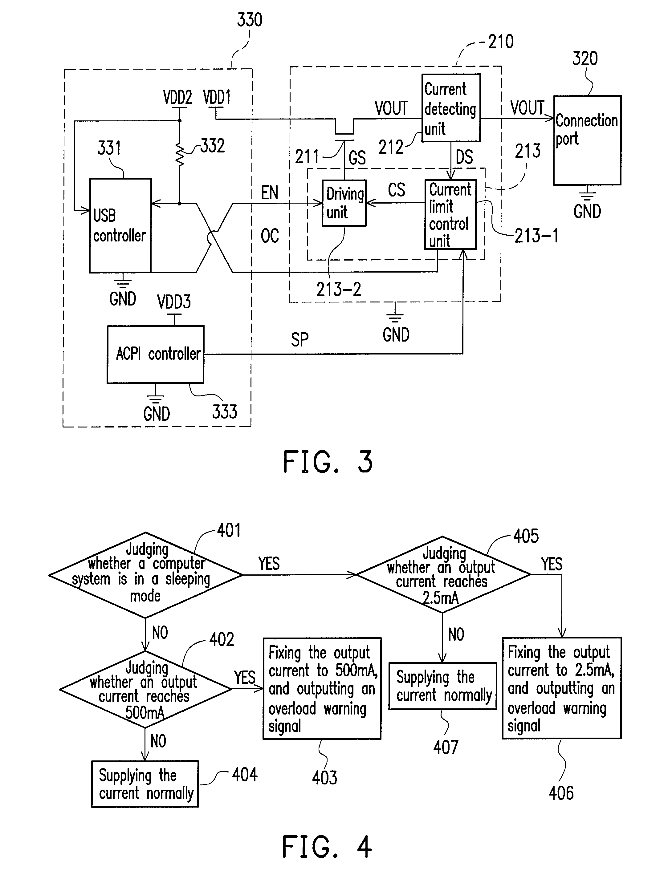
[0022]FIG. 2 is a block diagram illustrating a main circuit of a current limit protection apparatus according to an embodiment of the present invention. Referring to FIG. 2, the current limit protection apparatus 210 mainly includes a MOS transistor 211, a current detecting unit 212 and a current limit circuit 213. One of a source / drain of the MOS transistor 211 is used for receiving a voltage VIN; and another one of the source / drain of the MOS transistor 211 is used for outputting a voltage VOUT. A gate of the MOS transistor 211 is used for receiving a gate driving signal GS to determine a conducting current of the MOS transistor 211. The current detecting unit 212 is used for detecting the conducting current of the MOS transistor 211, so as to generate a detecting result DS. The current limit circuit 213 includes a current limit control unit 213-1 and a driving unit 213-2. The current limit control unit 213-1 has a plurality of current threshold values. The current limit control u...


PUM


Abstract

A current limit protection apparatus and a method for current limit protection are provided. The current limit protection apparatus includes a MOS transistor, a current detecting unit, and a current limit circuit. Two source / drain of the MOS transistor are used for receiving a first-voltage and outputting a second-voltage respectively. A gate of the MOS transistor is used for receiving a gate driving signal to determine a conducting current of the MOS transistor. The current detecting unit is used for detecting the conducting current, so as to generate a detecting result. The current limit circuit has a plurality of current threshold values. The current limit circuit selects one of the current threshold values according to an indicating signal and generates the gate driving signal according to a difference between the selected current threshold value and the detecting result.

Description

BACKGROUND OF THE INVENTION[0001]1. Field of the Invention[0002]The present invention relates to a current limit protection apparatus and a method thereof. More particularly, the present invention relates to a current limit protection apparatus having a plurality of current threshold values and a method thereof.[0003]2. Description of Related Art[0004]FIG. 1 is a coupling diagram of a conventional current limit protection apparatus of a computer system. Referring to FIG. 1, the reference numeral 110 represents a conventional current limit protection apparatus; the reference numeral 120 represents a connection port for connecting a universal serial bus (USB) peripheral device; and the reference numeral 130 represents a circuit connected with the current limit protection apparatus 110 in the computer system. The circuit 130 includes a USB controller 131, a resistor 132 and supply voltages VDD1 and VDD2 provided by the computer system. Moreover, GND represents a common level.[0005]The ...

Claims


Application Information

Patent Timeline
Patent Type & Authority Patents(United States)
IPC IPC(8): H02H9/08
CPCG06F1/266
Inventor CHU, PING-YING
Owner NUVOTON
Why Eureka
Try Eureka