
Elastomeric damage-control barrier

a technology of elastomeric and barrier, applied in the field of protective coverings, can solve the problems of posing a great risk to the occupants of the marine vessel, chemical leakage hazard or fire hazard, and achieve the effect of reducing or minimizing the damage ensuing

Inactive Publication Date: 2010-09-14
NAVY THE UNITED STATES OF THE AMERICA AS REPRESENTED BY THE SEC OF THE
View PDF47 Cites 26 Cited by
  • Summary
  • Abstract
  • Description
  • Claims
  • Application Information

AI Technical Summary

Benefits of technology

The composite structure effectively resists ballistic penetration, limits rupture, and controls fluid leakage by forming a membrane that remains intact to prevent fluid ingress or egress, thereby minimizing damage and ensuring structural integrity.

Problems solved by technology

For instance, an explosive or ballistic event can puncture or otherwise rupture a marine vessel in at least one location, resulting in the rapid ingress of water and the concomitant sinking of the marine vessel, thus posing a great risk to the occupants of the marine vessel.
A liquid container or gas container (made of any structural material) that is leaking due to an explosive or ballistic event can represent a chemical leak hazard or a fire hazard (e.g., when the container is a tank containing gasoline).

Method used


Image

  • Elastomeric damage-control barrier
  • Elastomeric damage-control barrier
  • Elastomeric damage-control barrier

Examples


Embodiment Construction

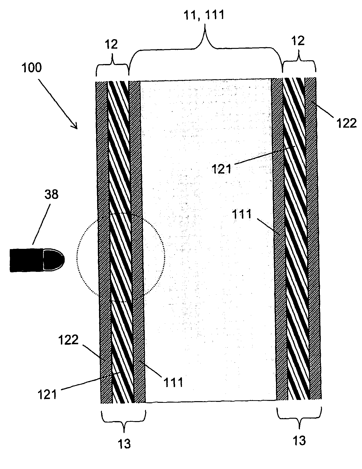
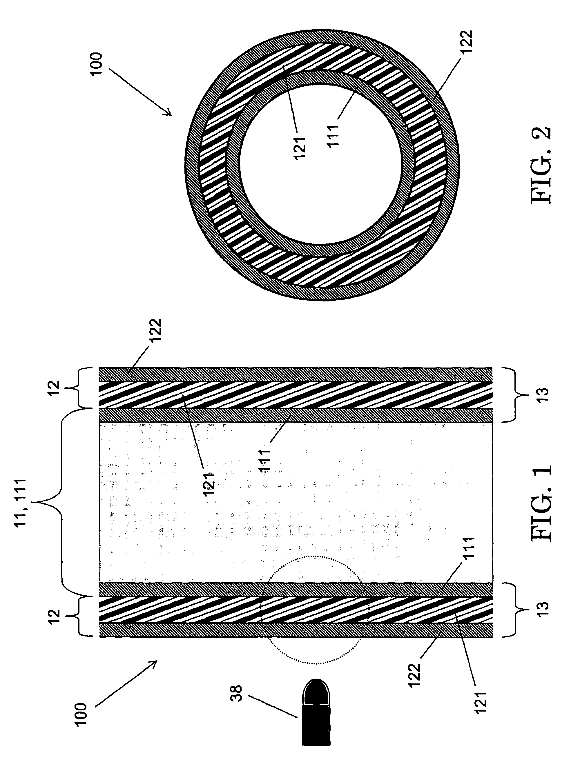
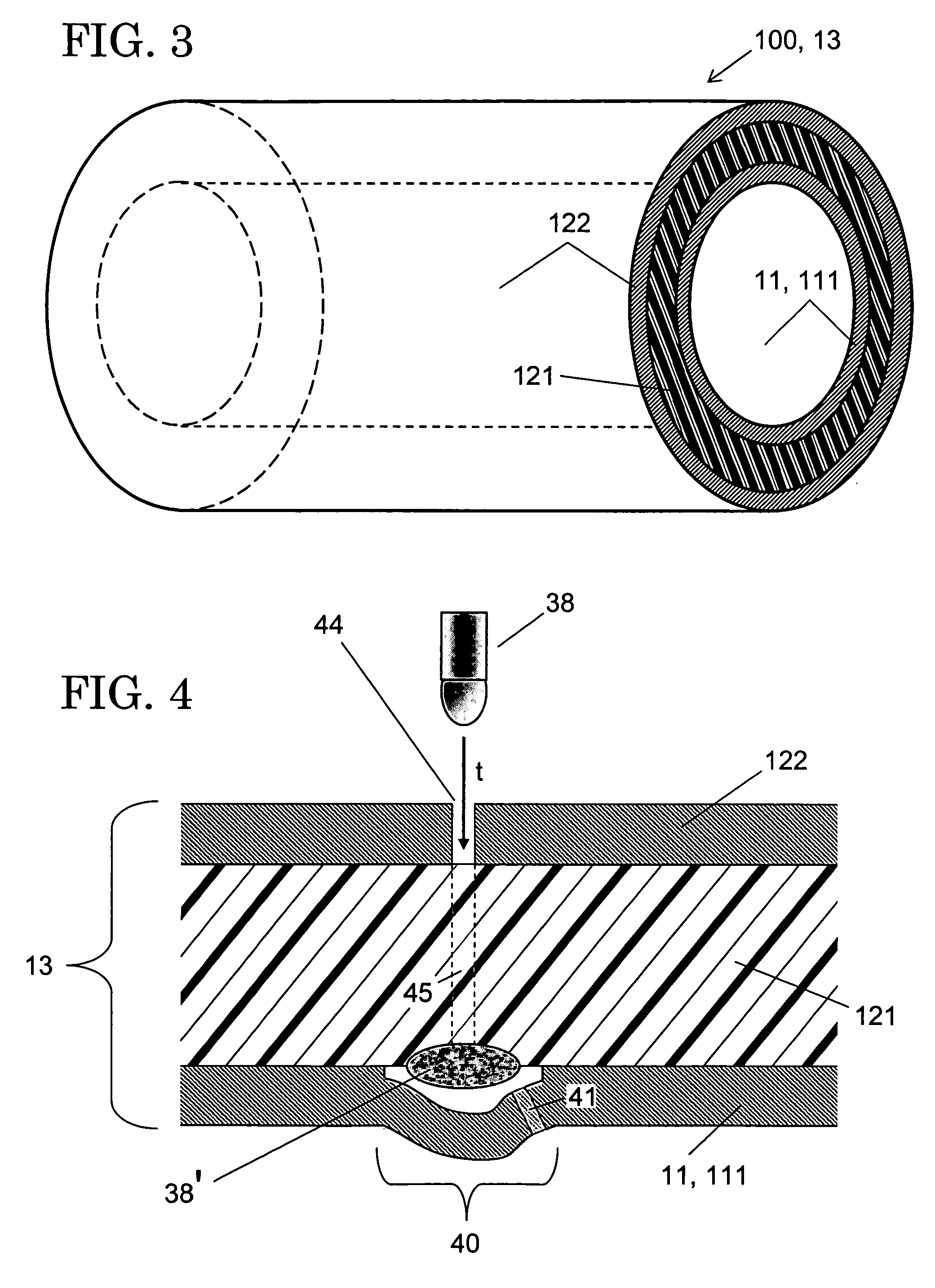
[0033]Referring now to FIG. 1 through FIG. 3, a conventional pipe 11 having a cylindrical metal pipe wall 111 is covered with a cylindrical protective barrier 12 in accordance with the present invention. Protective barrier 12 includes an elastomeric layer 121 and a cylindrical metal sleeve 122, the elastomeric layer 121 being situated intermediate the pipe wall 111 and the sleeve 122. Elastomeric layer 121 is composed of a polymer (e.g., polyurea or polyurethane) characterized by high strain-rate sensitivity (strong strain-rate sensitivity). The present invention's combination 10, which includes the pipe 11 and the present invention's protective barrier 12, thus represents a laminar material system that includes three adjacent layers. In this multilayer system, a highly rate-sensitive elastomeric layer 121 is sandwiched between two “rigid” (i.e., more rigid than the elastomer of layer 121) layers, viz., pipe wall 111 and sleeve 122.

[0034]Still referring to FIG. 1 through FIG. 3 and ...


PUM

PropertyMeasurementUnit
Young's modulusaaaaaaaaaa

Abstract

A typical inventive embodiment describes a tubular shape and comprises a rigid outer layer, an elastomeric middle layer and a rigid inner layer. The elastomeric material is a strain-rate-sensitive polymer (e.g., polyurethane or polyurea) having a Young's modulus of approximately 700-1000 psi at 100% strain, and strong strain-rate-sensitivity in approximately the 103 / second-106 / second range. By the time that the projectile reaches the rigid inner layer, a projectile that impacts the three-layer system (commencing at the rigid outer layer) is structurally and kinetically diminished in its destructiveness by the rigid outer layer together with the elastomeric middle layer. Furthermore, the elastomeric middle layer becomes more rigid during a brief period in which it absorbs energy from the projectile, then again becomes elastic in a manner formative of a membrane covering the rigid inner layer. The elastomeric membrane tempers leakage if rupturing of the rigid inner layer has occurred.

Description

CROSS-REFERENCE TO RELATED APPLICATIONS[0001]This application claims the benefit of U.S. provisional application No. 60 / 564,584, filed 23 Apr. 2004, hereby incorporated herein by reference, entitled “Armor Including a Strain Rate Hardening Elastomer,” joint inventors Roshdy George S. Barsoum and Philip Dudt.[0002]This application is a continuation-in-part of U.S. nonprovisional application no. 10 / 864,317, filed 10 Jun. 2004, hereby incorporated herein by reference, entitled “Armor Including a Strain Rate Hardening Elastomer,” joint inventors Roshdy George S. Barsoum and Philip Dudt, now U.S. Pat. No. 7,300,893 B2, issue date 27 Nov. 2007, which claims the benefit of the aforesaid U.S. provisional application No. 60 / 564,584, filed 23 Apr. 2004, entitled “Armor Including a Strain Rate Hardening Elastomer,” joint inventors Roshdy George S. Barsoum and Philip Dudt.[0003]This application claims the benefit of PCT application (international application published under the Patent Cooperati...

Claims


Application Information

Patent Timeline
Patent Type & Authority Patents(United States)
IPC IPC(8): B65D39/00B32B27/04F41H5/04F41H5/06B29C70/70D06M23/00
CPCB29C70/70B32B3/10F41H5/0428F41H5/0492B29K2995/0089Y10S428/912Y10T428/1386Y10T428/139Y10T428/1352Y10S428/911Y10T442/2623Y10T442/20Y10T442/2615B32B2375/00B32B2571/02B32B2260/046B32B27/42B32B27/40
Inventor DUDT, PHILIP JOHNBARSOUM, ROSHDY GEORGE S.
Owner NAVY THE UNITED STATES OF THE AMERICA AS REPRESENTED BY THE SEC OF THE
Learn More