
Electric actuator

a technology of actuators and actuators, applied in the direction of rotating magnets, synchronous machines with stationary armatures, magnetic circuits characterised by magnetic materials, etc., can solve the problems of reducing system efficiency, increasing system costs, and losing several percent of the power going through the transmission. , to achieve the effect of high force or torque and high magnetic permeability material

Inactive Publication Date: 2010-09-14
WITTIG MICHAEL
View PDF19 Cites 23 Cited by
  • Summary
  • Abstract
  • Description
  • Claims
  • Application Information

AI Technical Summary

Benefits of technology

[0008]According to one embodiment, an electric actuator is provided comprising windings constructed from a conductive core of high magnetic permeability material surrounded by an electrical insulator. The conductive core simultaneously carries an electric current and a magnetic field, resulting in an actuator that may develop a high force or torque for its size compared to conventional electric actuators.

Problems solved by technology

Transmissions add sources of failure, increase the cost of the system, and reduce system efficiency.
It is not uncommon, for example, to lose several percent of the power going through a transmission, primarily as a result of friction.
Transmissions also typically add other unwanted problems.
Gear transmissions usually add backlash, which is mechanical play between meshing gear teeth.
When precision control of a system is attempted, such as in a robotic or machine tool application, this mechanical play can cause a great deal of problems.
Again, the torque gains for such a design for a given motor size may not be significantly increased.

Method used


Image

  • Electric actuator
  • Electric actuator
  • Electric actuator

Examples


Embodiment Construction

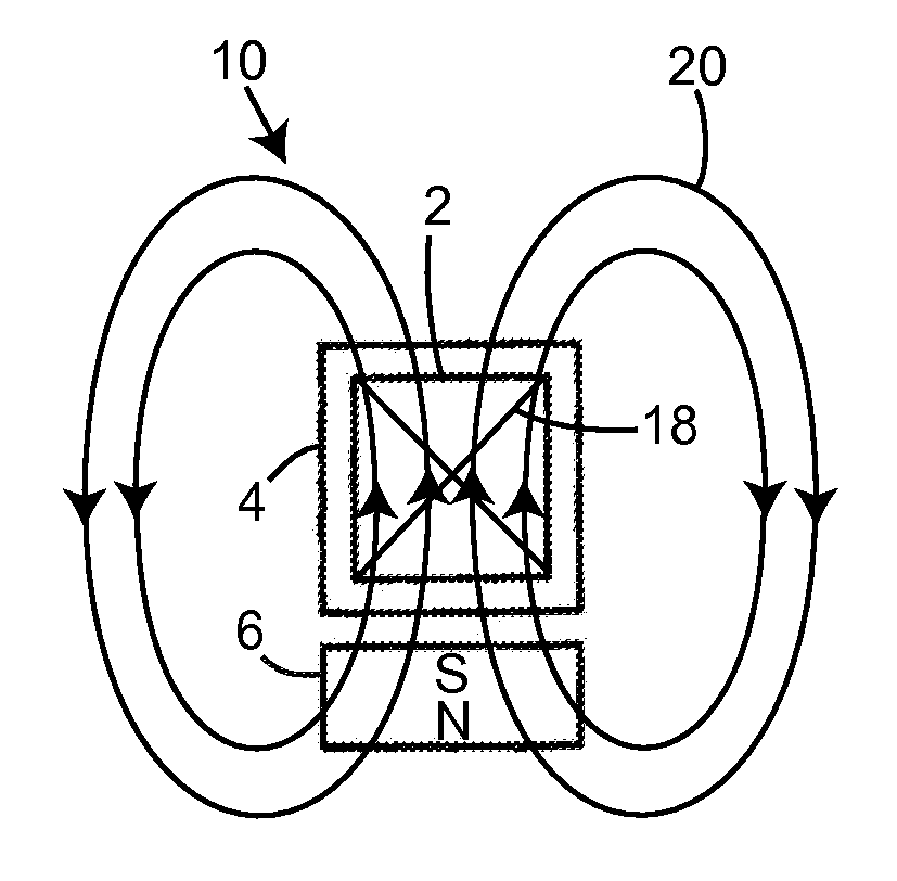
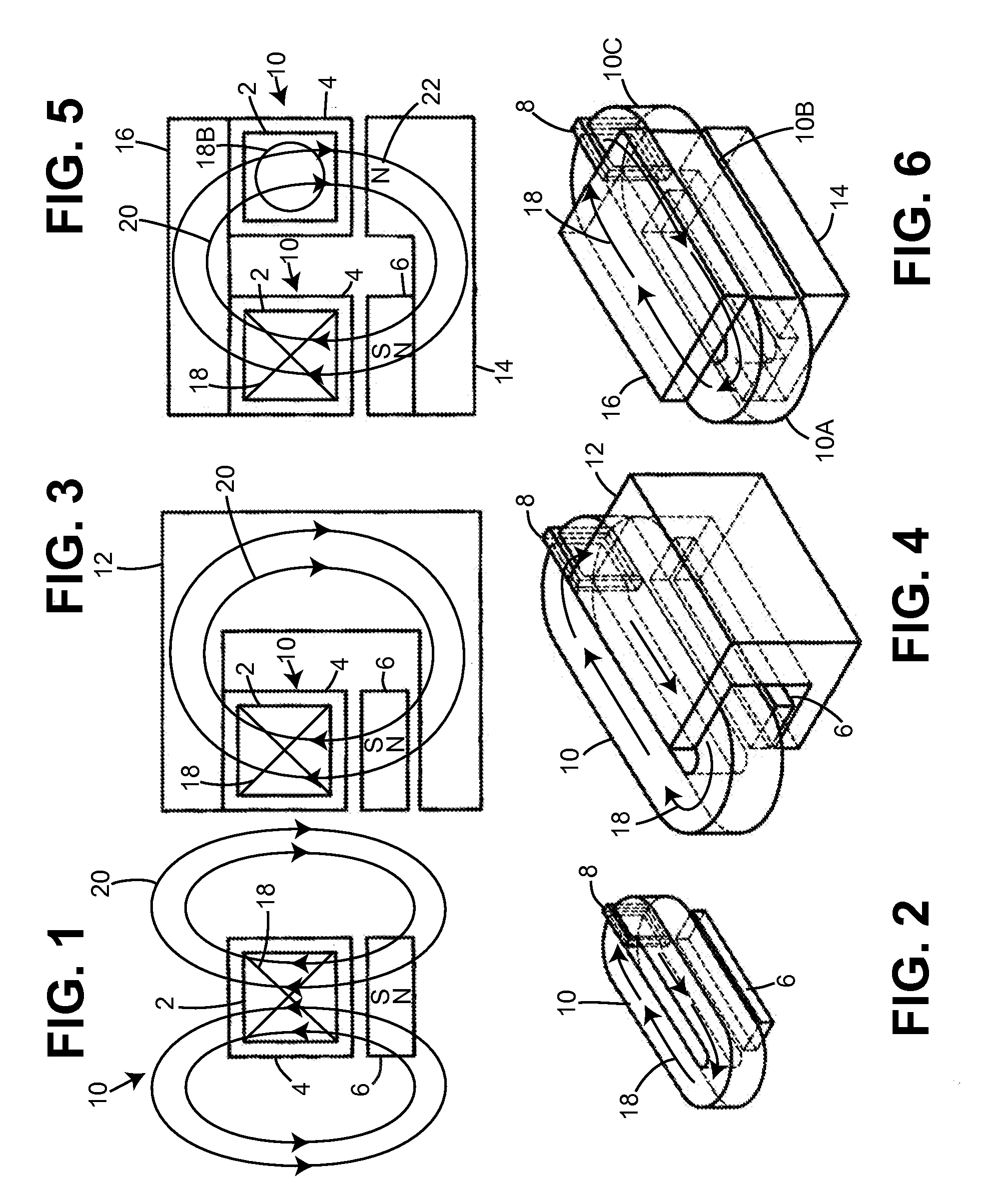
[0056]FIG. 1 of the accompanying drawings illustrates an electric actuator according to one embodiment. A wire 10 is comprised of electrical insulation 4 of at least 1 ohm-m of resistance and at least 50 volts / 0.001 inch dielectric strength, preferably lacquer of the type used to insulate magnet wire, covering a conductive high permeability core 2 that is carrying a current 18. Conductive high permeability core 2 is composed of a material with a high magnetic permeability, high magnetic saturation flux density, and a high electrical conductivity. Preferably, the material of conductive high permeability core 2 has an electrical resistance of less than 4×10^−7 ohm-m, a magnetic permeability relative to air of at least 100, and a magnetic saturation flux density of at least 1 Tesla. An exemplary material is purified iron (Fe) of at least 99.98% purity. Electric current 18 is represented by an ‘X’ because this is the typical notation used to represent current flowing into the page (an ‘...


PUM


Abstract

According to one embodiment, an electric actuator is provided comprising windings constructed from a conductive core of high magnetic permeability material surrounded by an electrical insulator. The conductive core simultaneously carries an electric current and a magnetic field, resulting in an actuator that can develop a high force or torque for its size compared to conventional electric actuators.

Description

CROSS-REFERENCE TO RELATED APPLICATIONS[0001]This application claims priority from U.S. provisional application No. 60 / 585,286, filed on Jul. 2, 2004, U.S. provisional application No. 60 / 617,947, filed Oct. 9, 2004, and U.S. provisional application No. 60 / 622,667, filed on Oct. 26, 2004. This application incorporates the disclosures of all of the aforementioned applications by reference herein.BACKGROUND[0002]1) Field[0003]These embodiments relate to electric actuators and more specifically to the construction of their current-carrying portions.[0004]2) Discussion of Related Art[0005]Electric actuators are often used in, for example, automobiles to actuate seats, mirrors, and windshield wipers. Electric motors, such as those found in the aforementioned automobile components, and voicecoil actuators, such as those found in speakers, are typical forms of an electric actuator. Other forms of electric actuators include linear motors, such as those used in the machine tool industry.[0006...

Claims


Application Information

Patent Timeline
IPC IPC(8): H02K1/00
CPCH02K1/141H02K3/04H02K3/26H02K3/47H02K15/0421H02K21/24H02K21/44H02K23/54H02K23/56H02K1/02
Inventor WITTIG, MICHAEL BRIAN
Owner WITTIG MICHAEL
Learn More