
Passive sensor system for detection of wear problems in paper machine clothing

a sensor system and wear problem technology, applied in the field of passive sensor system for detection of wear problems in paper machine clothing, can solve the problems of paper machine clothing wear, difficulty in streamlined manufacturing process, and difficulty in providing a stratified press fabric free of needle tracks,

Active Publication Date: 2010-09-21
ALBANY INT CORP
View PDF38 Cites 7 Cited by
  • Summary
  • Abstract
  • Description
  • Claims
  • Application Information

AI Technical Summary

Benefits of technology

The present invention is a special fabric used in paper making that has a sensor system to detect wear and tear. The fabric has two layers - a base fabric and a fine fabric. The base fabric is made of staple fibers that are colored to indicate wear, while the fine fabric is made of smaller staple fibers that are not colored. The fine fabric prevents the coarser fibers from being transported up to the paper-contacting surface of the fabric. This special fabric helps to improve the efficiency and lifespan of the paper making process.

Problems solved by technology

Needless to say, this requirement makes it difficult to streamline the manufacturing process, as each press fabric must typically be made to order.
Unfortunately, where the press fabric has a stratified batt structure, this reverse needling forces coarse fibers from within the press fabric to the surface.
This compromises the smooth pressure distribution otherwise obtained by the fine surface layer, since coarse fibers are brought up to the surface, and makes it difficult to provide a stratified press fabric that is free of needle tracks.
Further, paper machine clothing wears out and requires replacement through normal use.
Such surface wear often results in a reduction in the quality of the produced paper (e.g. a worn fabric may cause marking of the paper).

Method used


Image

  • Passive sensor system for detection of wear problems in paper machine clothing
  • Passive sensor system for detection of wear problems in paper machine clothing
  • Passive sensor system for detection of wear problems in paper machine clothing

Examples


Embodiment Construction

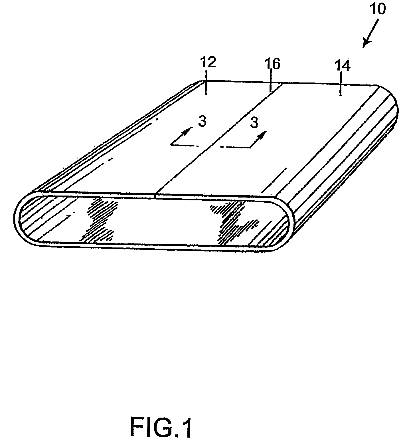
[0033]Turning now to these figures, FIG. 1 is a schematic perspective view of the press fabric 10 of the present invention. Press fabric 10 is of the on-machine-seamable variety and takes the form of an endless loop once its two ends 12,14 have been joined to one another at seam 16.

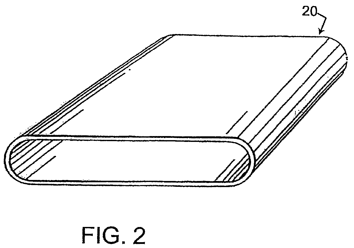
[0034]In an alternate embodiment, as shown in schematic perspective view in FIG. 2, press fabric 20 has no seam and is in the form of an endless loop.

[0035]FIG. 3 is a cross-sectional view taken as indicated by line 3-3 in FIG. 1. Press fabric 10 includes a base fabric 30. In general, the base fabric 30 may be a woven, nonwoven, nonwoven arrays of MD or CD oriented yarns, knitted or braided structure of yarns of the varieties used in the production of paper machine clothing, such as monofilament, plied monofilament and / or multifilament yarns extruded from polymeric resin materials. Resins from the families of polyamide, polyester, polyurethane, polyaramid and polyolefin resins may be used for this purpose...


PUM

PropertyMeasurementUnit
angleaaaaaaaaaa
widthaaaaaaaaaa
widthaaaaaaaaaa

Abstract

A stratified press fabric for the press section of a paper machine having a passive sensor system for detecting wear in the press fabric. The lower (non-surface) layer(s) of the stratified press fabric are produced using colored staple fiber batt material. As the surface of the fabric is worn away through use, the colored batt material is exposed to provide a visual indication of the wear. This visual indication allows the customer to readily determine the appropriate time to replace the press fabric.

Description

FIELD OF THE INVENTION[0001]This application is a 371 of PCT / US2003 / 039438 filed on Dec. 11, 2003, published on Jul. 7, 2005 under publication number WO 2005 / 061787 A1. In addition, this application is a continuation-in-part of U.S. patent application Ser. No. 10 / 295,085 filed Nov, 15, 2002 entitled “Stratified Press Fabric,” which was granted as U.S. Pat. No. 7,407,564 on Aug. 5, 2008.BACKGROUND OF THE INVENTIONDescription of the Prior Art[0002]During the papermaking process, a cellulosic fibrous web is formed by depositing a fibrous slurry, that is, an aqueous dispersion of cellulose fibers, onto a moving forming fabric in the forming section of a paper machine. A large amount of water is drained from the slurry through the forming fabric, leaving the cellulosic fibrous web on the surface of the forming fabric.[0003]The newly formed cellulosic fibrous web proceeds from the forming section to a press section, which includes a series of press nips. The cellulosic fibrous web passes ...

Claims


Application Information

Patent Timeline
Patent Type & Authority Patents(United States)
IPC IPC(8): D21F7/08B32B5/02D21F1/30
CPCD21F1/30D21F7/083Y10T428/24942Y10S162/90Y10T442/3724Y10T442/3732
Inventor HANSEN, ROBERT A.
Owner ALBANY INT CORP
Learn More